This thread has been locked.

If you have a related question, please click the "Ask a related question" button in the top right corner. The newly created question will be automatically linked to this question.

DRV8703-Q1: high-side gate and the high-side source falling waveform

Part Number: DRV8703-Q1


Hi,

The waveforms of the high-side gate and the high-side source are different for the two DRV8703-Qs.

I would like to know the reason for this.

The waveforms below are the measured dead time of the H-bridge circuit with two DRV8703-Qs, respectively.

The high-side gate is yellow and that of the high-side source is green.


In each waveform, it was confirmed that the MOSFET is turned off because the Vgs of the high-side N-channel MOSFET is 0V.

However, one is falling smoothly, while the other is falling steeply.

I would like to know why the falling waveforms are different on the two DRV8703-Qs.


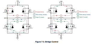
The H-bridge circuit is shown in the figure below.

The measurement points of the waveform are the gate and source of Q4.

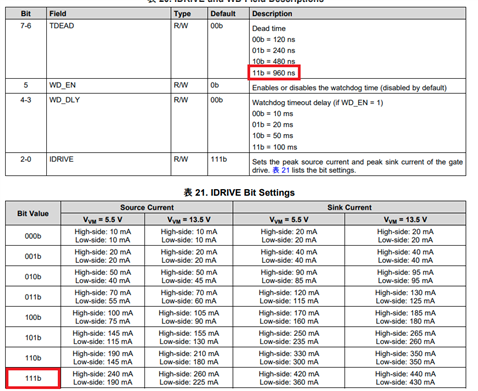
The TDEAD and IDRIVE settings for the two DRV8703-Qs are the same.

The red boxes in the figure below are the setting values.


Regards,

  • Hi,

    Thank you for your question. Let me investigate and feedback to you within 24hours.

    regards

    Shinya Morita

  • The waveforms of the high-side gate and the high-side source are different for the two DRV8703-Qs.

    I would like to know the reason for this.

    Hello Sota,

    1. Why would you want such a long Dead-time of 1000ns? Too much deadtime is not good as it causes distortion to motor current, and so I suggest to reduce it to minimum as long as the 2 FETs are not crossing each other. During this deadtime, SH1 (Q4 Source) signal is floating and so the said signal can have any voltage value, depends on the state of the other half bridge (CH2) and the BEMF of the motor. 

    2. Here is what I think: top pic shown a ramping down of SH1 during deadtime and this is normal as SH1 was pulling down by 0v on SH2. Bottom pic shows SH1 floating at about 30V due to motor BEFM during coasting, or because SH2 was floating due to CH2 FETs are not working . If you're interested on this, then please post waveform of SH2 together with SH1 then it is easy to see why.

    Regards,

    Brian

  • Hi,

    I think top and bottom waveform were measured in different condition of motor current and SH conditions. Like follows, depending on motor current, we see some different. 

    I suggest to measure SH1 pin and motor current at the same time with GH1 and GL1. Then we can check how we see the difference.

    regards

    Shinya Morita

  • I suggest to measure SH1 pin and motor current at the same time with GH1 and GL1. Then we can check how we see the difference.

    Hi,

    Sota posted the waveform of SH1 together with GH1 and GL1, and I suggested that without knowing the voltage at SH2 then we really can't expect what SH1 should be looked like because SH1 depends on SH2 during the deadtime with both H and L FETs are off.

    The current flows through SH1 is just the mirror image of voltage at SH1. 

    Brian

  • Hi 

    Thank you for your post

    regards

    Shinya Morita

  • Hi Brian,

    Thank you for the advice.

    1. Why would you want such a long Dead-time of 1000ns? Too much deadtime is not good as it causes distortion to motor current, and so I suggest to reduce it to minimum as long as the 2 FETs are not crossing each other. During this deadtime, SH1 (Q4 Source) signal is floating and so the said signal can have any voltage value, depends on the state of the other half bridge (CH2) and the BEMF of the motor.

    I think you are right. I will reconsider the dead time.

    2. Here is what I think: top pic shown a ramping down of SH1 during deadtime and this is normal as SH1 was pulling down by 0v on SH2. Bottom pic shows SH1 floating at about 30V due to motor BEFM during coasting, or because SH2 was floating due to CH2 FETs are not working . If you're interested on this, then please post waveform of SH2 together with SH1 then it is easy to see why.

    I will measure it and post the results.
    Unfortunately, I don't have a measurement environment right now. So it will take some time to post the results.

    Regards,

    Sota

  • Hi Shinya-san,

    Thank you for your suggestion.

    I have an extra CHs on my oscilloscope, so I will measure the current at the same time when I do the measurements suggested by Brian.

    Regards,

    Sota

  • Hi Sota,

    Thank you for your update.

    regards

    Shinya Morita