Hi support team.
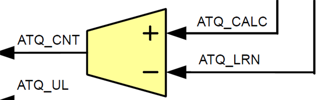
I think that ATQ_CALC and ATQ_CNT are reversed in the auto torque block diagram.
Is this correct?
Regards,
Higa
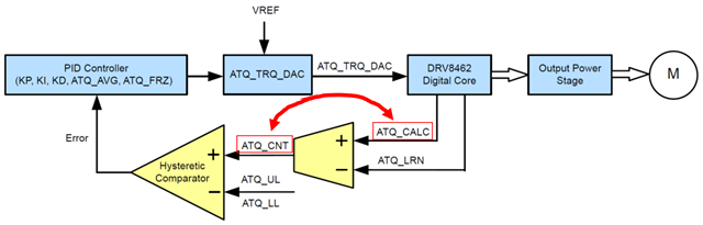
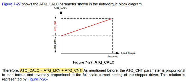
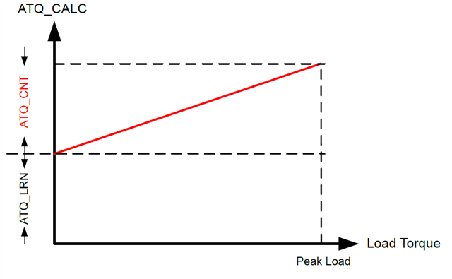
ATQ_CALC=ATQ_LRN+ATQ_CNT
Hi support team.
I think that ATQ_CALC and ATQ_CNT are reversed in the auto torque block diagram.
Is this correct?
Regards,
Higa
ATQ_CALC=ATQ_LRN+ATQ_CNT