This thread has been locked.

If you have a related question, please click the "Ask a related question" button in the top right corner. The newly created question will be automatically linked to this question.

DRV8701: EMI Radiated Emissions 100Mhz

Part Number: DRV8701
Other Parts Discussed in Thread: DRV8705-Q1

I have trouble passing CISPR11 EMI testing with a board designed for 3 drives with DRV8701 ICs. I looked at two other similar posts and gone through the same tests. The test fails with the motors disconnected, it fails without pwm, the only way to pass is when the drive is in sleep. The Idrive is at 12.5 / 25 mA with 33kOhms, which is as low as it goes with the fets I am using. The capacitors are set as per the datasheet and it is a 4 layer board with ground directly underneath, the caps are close to the chip. Using near field probes I find the same frequencies that were found in the chamber at 3 meters. The peaks are found when the probe is directly over the AVDD and DVDD capacitors as well as the charge pump capacitors. I cannot determine for sure that the noise is comming from the regulators or the charge pump. I tried adding smaller capacitors in parallel to the AVDD DVDD to no avail, adding capacitor to the charge pump output did not solve it either. I am near certain the DRV8701 is the cause of the 100Mhz noise, I think it couples to VM or Ground and is emitted through the battery leads that are long enough to act as an antenna. 

Is there any way to filter the noise the regulators or charge pump?

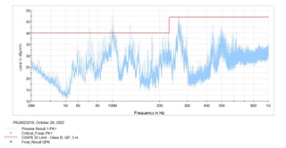
Results of far field:

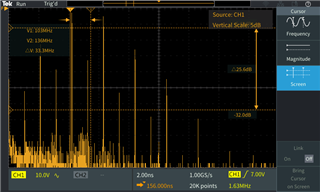
Results of near field:

  • Mathieu,

    Please allow me 24 hours to look for some data.

    Regards,

    Ryan

  • Mathieu,

    One thing to try is to add a PI filter on the power supply line to rule out your suspicion.  

    If you disable 1 or 2 of the 3 drivers, do the emissions reduce?  

    We typically add these filters on our automotive devices and also use spread spectrum clocking internally to reduce noise from the internal clocks.  This is from the DRV8705-Q1 EVM which is basically an automotive version of the device you are testing.

    L1 is a 2.2uH inductor.  Full schematic can be found online.

    https://www.ti.com/tool/DRV8705H-Q1EVM

    Regards,

    Ryan

  • Disabling drives improves the emissions, still with only one it is above the threshold. I will look into changing for a spread spectrum drive and adding filters. 

    Since I have 3 indentical drives, would one common filter work (there can only be a single one powered at a time)? They are quite spread apart on the board, but the main antenna is a long battery lead. 

    Thank you