This thread has been locked.

If you have a related question, please click the "Ask a related question" button in the top right corner. The newly created question will be automatically linked to this question.

BLDC Motor Control Development Board for a 2 Wheeler Hub Motor

Other Parts Discussed in Thread: DRV8300, LAUNCHXL-F280049C, DRV8701, DRV8353, DRV8353RS-EVM, LAUNCHXL-F280025C

Hi,

Need to start a BLDC motor control product development , new project.

This is for  a 350W, 48V  and 60V BLDC Hub motor for 2 Wheeler application.

Motor has Hall sensor feedback..

Can we go for a simple 6 Step control Algorithm ?

Jerk free and noise free performance especially during starting is important.

Please suggest a suitable TI solution...

Regards,

Anil

  • Hi Anil,

    Thanks for your question!

    For a 48V and 60V application the 2 drivers that would be the best suited is the DRV835x or the DRV8300. The DRV835x has more diagnostics and fault protection compared to the DRV8300, but the DRV8300 is a simpler device and comes in a smaller package. 

    Are there any automotive safety standards that this design needs to conform to (for example ISO26262)? If so, then the DRV325x-Q1 may be better suited for your needs. 

    As far as control algorithm, 6 step trapezoidal control will be the simplest method with good torque performance, however it has more torque ripple compared to Field Oriented Control (FOC). FOC will be the quietest and smoothest, but the FOC algorithm is quite complex compared to 6 step trapezoidal control, so you may try with 6 step trapezoidal control first to see if it meets your requirements. 

    Regards,

    Anthony Lodi

  • Hi Anil,

    This is for  a 350W, 48V  and 60V BLDC Hub motor for 2 Wheeler application.

    Motor has Hall sensor feedback..

    Can we go for a simple 6 Step control Algorithm ?

    Jerk free and noise free performance especially during starting is important.

    So the wheel hub motors are direct drive and no additional gear down added for higher torque? 

    Both driver chips DRV835x or the DRV8300 that Anthony suggested have the input de-glitch noise filter, and this causes the output signals to dither even when inputs are not changing. The dithering output waveform cause the audible noise.

    Brian

  • Thanks Anthony for the details...

    DRV8300 should be OK for us.

    No need to conform to automotive standards as of now.

    Could you please suggest TI development boards (both micro controller and driver boards)  using which I can  quickly start my development.

    Please suggest both 6 step and FOC development boards

    Regards,

    Anil

  • Hi Brian,

    Hub Motors are direct drive.   No additional  Gear added.

    See one in the link below

    https://www.amazon.com/Kee-nso-Electric-Bicycles-Scooter/dp/B083M49KRB/ref=sr_1_8?keywords=Electric+Hub+Motor&qid=1672832267&sr=8-8

    Audible noise will not be acceptable. Is there a way to bypass this feature ?

    Regards,

    Anil

  • Hi Anil,

    Please use the link below to find the DRV8300EVM to evaluate the DRV8300. The DRV8300EVM works in conjunction with the LaunchXL-F280049C microcontroller. Unfortunately the EVM doesn't support FOC control, but it does have 6 step sensored trapezoidal control for you to test out. 

    https://www.ti.com/tool/DRV8300DIPW-EVM

    Regarding the input deglitch filter for the inputs, I am not aware of this filter causing dithering on the output waveform. The input deglitch filter is simply to avoid the outputs changing due to noise on the inputs. There is a deglitch time so that the input needs to change state for a particular length of time before the output will change. The input deglitch should actually prevent dithering, since the outputs don't change due to high frequency noise on the inputs. This is a feature that you want to have.

    Regards,

    Anthony Lodi

  • Hi Anthony,

    Regarding the input deglitch filter for the inputs, I am not aware of this filter causing dithering on the output waveform. The input deglitch filter is simply to avoid the outputs changing due to noise on the inputs. There is a deglitch time so that the input needs to change state for a particular length of time before the output will change. The input deglitch should actually prevent dithering, since the outputs don't change due to high frequency noise on the inputs. This is a feature that you want to have.

    I used the DRV8701 with the input deglitch feature, and it caused me more headache than help to drive the motor better. Here is the thread if you're interested. Keep in mind that the measured jitter on the gate driving signals were done with keeping the PWM inputs constant. 

    https://e2e.ti.com/support/motor-drivers-group/motor-drivers/f/motor-drivers-forum/1161554/drv8701-h-bridge-driver

    Brian

  • Audible noise will not be acceptable. Is there a way to bypass this feature ?

    No, according to TI engineers and my experience. The engineers screwed up, or they thought the noise was ok for some application, like noisy drones or fans.

    Edit: I looked at the motor listed on Amaz, it is an inside-out BLDC. The said dithering on the gate signal causes a humming noise but I don't think the scooter user would notice it, unless he is 007 agent on a super silent mission. In my case, the motor humming is on a movie lens and the user and the audio recorder is very close.

    Brian

  • Thanks Anthony.

    Can you also please recommend a FOC  control solution (for PMSM - Sinusoidal motor) - Microcontroller  Board + Driver board?.

    Any driver IC is OK. Need to support 48V  battery , 350W+ PMSM motor.

    Could you see one MSP430 based solution ? Is that the cheapest solution ?

    Regards,

    Anil

  • Thanks a lot Brian for the information. Plan is to test with Development board. Will definitely look at the points you mentioned and see whether it is an issue for our application.

    Regards,

    Anil

  • Hi Anil,

    The DRV8353RS-EVM (which comes with the F28027F MCU) has sensorless FOC code available for evaluation. The DRV8353 can operate up to 100V (VDRAIN voltage) and up to 80V for VM voltage. 

    We don't currently have any demo boards that uses the MSP430 for FOC; the C2000 microcontrollers have more mature solutions for FOC so that is what we currently use. 

    One note: Please make sure that you change the IDRIVE setting on the DRV8353RS-EVM to the lowest IDRIVE setting to avoid damaging the FETs/driver on the EVM. The FETs on the EVM have a very low Qgd, so a low IDRIVE current is needed so that the MOSFETs are not switched on too fast. Anytime the device is powered up, or there is an undervoltage event, or the device comes out of sleep mode, the IDRIVE setting needs to be changed back to the lowest setting over SPI (since the SPI registers get reset to the default values during undervoltage or sleep mode). 

    Regards,

    Anthony Lodi

  • Hi Brian,

    Thanks for the explanation, now I understand what you meant by dithering. I will keep that in mind. The mismatch between the MCU clock and the DRV clock will effect the duration of the jitter. Additionally, the frequency of the DRV sampling the outputs (which would be dependent on the device clock frequency) would effect the duration of the jitter. I haven't seen this being a major issue in the past with customers, but I can see that there could be certain applications where this could be more important. I will keep that in mind.

    Regards,

    Anthony Lodi

  • Hi Anthony,

    The mismatch between the MCU clock and the DRV clock will effect the duration of the jitter.

    The pwm inputs are asynchronous to the DVR internal clock, but this should not cause the jittering outputs if these pwm input are driving the internal FETs directly to generate the gate driving signals. TI engineers re-sampled the pwm input in the De-glitch circuit, and this created the jitter - because the internal clock frequency is not high enough is my guess (temporal quantization). 

    Brian

  • Thanks a lot,  Anthony

    Will order these 2 sets of boards after doing some more studies on these.

    Regards,

    Anil

  • Sounds good Anil! Let me know if you have any questions.

    Regards,

    Anthony

  • Hi Anthony,

    I purchased DRV8353RS-EVM (with the F28027F MCU daughter card). Realized TI is not supporting firmware with HALL sensor  for this EVM. Could run motor in sensorless FOC algorithm with the default code provided.

    As mentioned in the beginning of this thread, ours is a 2W application with Hall sensor. Need low speed performance and good starting torque.

    Please suggest how to go about on this...

    Regards,

    Anil

  • Hi Anil,

    Realized TI is not supporting firmware with HALL sensor  for this EVM. Could run motor in sensorless FOC algorithm with the default code provided.

    For your Wheel Hub motor application, which is a stop and go, then running the motor with sensorless will not work for you. You need to use sensor mode in this case.

    Brian

  • Hi Anil,

    Understood, my recommendation would be to try sensorless at least initially to see the performance, and if you want to take it a step further you could order the LaunchXL- F280025C to allow you to use the Universal Motor Control Project code in the MotorControl SDK which has an option for hall-based sensored FOC. This can be used with the DRV8353RS-EVM. For more information on the Universal Motor Control Project, please see the User's Guide: ti.com/lit/ug/spruj26/spruj26.pdf?ts=1674744159457&ref_url=https%253A%252F%252Fwww.google.com%252F


    Anthony

  • Hi Anthony,

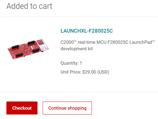
    I need to order below item? . This will  fit into the existing DRV8353-RS EVM driver board , right ?  Looking at the picture of this board, it has 4 sets of  interfacing connectors. DRV8353 driver board - EVM has only 2.  Hope only 2 are used.    Please cofirm.

    I will look  more into the Universal Motor Control project and get back with clarifications if any.

    Thanks & Regards,

    Anil

  • Hi Anil,

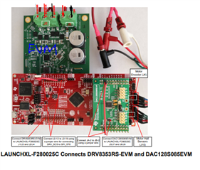
    The EVM only uses 2 of the interfacing connectors as shown in the image below. You can find more detail on how to connect and set up the DRV8353RS-EVM board with the LaunchXL-F280025C in section 2.2.6 of the Universal Motor Control project User's Guide. 


    Regards,

    Anthony Lodi

  • Thanks Anthony.

    Regards,

    Anil

  • Your welcome!

    Regards,

    Anthony

  • Hi Anthony,

    I just received my Launchxl-   25C board. While trying to connect , I see both DRV8353 EVM and 25C board have female connectors ...

    How are these 2 plugged ?

    Regards,

    Anil

  • Hi Anil,

    The DRV8353 EVM will connect underneath the Launchxl-F280025C as shown in Figure 2-8 of the User's guide. Please see section 2.2.6 of the User's guide for more information on how to connect the EVM for use with the Universal Motor Control lab. 

    Regards,

    Anthony Lodi

  • Hi Anthoy,

    As mentioned in previous message , both boards have female headers.   User guide or Board Assembly is wrong. 

    See board picture below... Connector is highlighted ...in red line

    I have lost so much time

    1.  By ordering wrong  daughter card - 27C

    2. DRV8353RS board was faulty / failed. I see many people reporting GDF failure in forum

    3. Ordered 25C board . Now I can not use this board also..

    Please suggest  how to proceed ...

    Regards,

    Anil

  • Hi Anil,

    I am sorry to hear of the difficulties you have run into! It looks like 2 100mil 20x2 male-to-male headers are needed as an adapter to connect the DRV8353RS-EVM to the F280025C. As a note, you will need to bend or cut one of the leads on the male to male header for pin 1 on J1 header of the EVM since it is a no-connect.

    The key to avoiding a GDF failure with the DRV8353RS EVM is to use the lowest IDRIVE settings when operating the EVM. The Qgd of the FETs is very small, so using a higher IDRIVE can increase the risk of causing gate driver damage due to ringing. 

    Regards,

    Anthony Lodi

  • Hi Anthony,

    Arranged male to male header.  Plese include this information  in  Figure 2-8 of the User's guide. 

    I will start testing on Motor once I receive my new DRV8353RS-EVM that I have ordered. 

    Btw, I never changed drive setting when tested previous board  with F28027F MCU.  Used orginal formware and GUI default values.  I assume lowest IDRIVE setting is the default one. Is that true ?  If yes,   how  I would have  got GDF fault. ?

    Also, I changed both DRV IC and  one of the Mosfets (which was showing Gate to Source short) .  Now I dont get GDF fault. Motor does not rotate. I dont see any PWM pulses from DRV, though it gets PWM pulses from Microcontroller.  Any suggestions  how to make it work ?

    Regards,

    Anil

  • Hi Anil,

    I would need to check the default GUI value is for the IDRIVE setting to verify what the default value is. Keep in mind that an undervoltage event could reset the DRV registers, and the SPI device register default is max IDRIVE. 

    In the case where you are getting PWMs from the microcontroller but not from the output of the DRV, could you confirm that the enable pin is high and that the fault pin is high? Also you want to make sure that the MCU is not commanding both high side and low side MOSFETs of the same phase to be on at the same time. If this happens then the DRV will not allow the outputs to go high. 

    Regards,

    Anthony Lodi

  • Hi Anthony, 

    As you mentioned, might be an under voltage on DRV board side made the IDRIVE setting to reset to max IDRIVE and that caused the MOSFET to fail.

    I have a doubt regarding the connections in Fig 2-8 of User guide.

    As per this,  3.3V generated on F280025C board and 3.3V generated on  DRV board gets shorted through Booster pack header J1/pin1 , since we are shorting jumpers JP1, JP2 and JP3 using short link.  Is this allowed ?  Two 3.3V  Regulator outputs getting shorted .

    Pls comment.

    Regards,

    Anil

  • Hi Anil,

    You bring up an interesting point regarding the shorting of the 3.3V from the board and the 3.3V from the DRV. To be on the safe side it may be best to not connect the J1/pin 1 to the F280025C, Though it may not be detrimental to have them shorted. If they are shorted, there could be a condition where there could be more current drawn from one of the 3.3V supplies due to a difference in the voltages (if one was 3.3V and the other was 3.1V there would be more current draw from the 3.3V supply). 

    Regards,

    Anthony

  • Hi Anthony,

    Sorry for  getting back  late on this. I started testing without shorting 3.3V from both sides..

    Configured for Level 1 , Hall sensor based  algorithm. Was really struggling to get the 50 % offset values and 50% duty cycle PWM  outputs with this. 

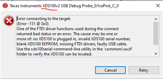
     CCS is showing programming error from yesterday. It was working for a week before that. 

    Error is 

     I used  command based debug tools of xds110.. Updated boot loader and firmware. I get below details with xdsdfu - e

    Device manager in my PC shows ...

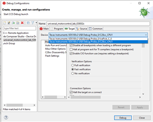
    CCS Debug configuration shows...XDS100 

    Please help to sort out this issue so that I can continue my  Lab project..

    Please note that CCS shows it as XDS100 where as everywhere else it XDS110.

    Thanks & Regards,

    Anil

  • Hi Anil,

    Thanks for your reply! Would you be able to select the "Ask a related question" and repost this as a separate question assigned to the C2000 microcontrollers forum?  The C2000 team will be more equipped to answer these types of questions, and I also believe it will be helpful for others to have this thread be a bit more focused on one particular issue. 

    Regards,

    Anthony 

  • Hi Anthony.

    Agree with you. Have done that...

    Regards,

    Anil

  • Thanks Anil!

    Regards,

    Anthony Lodi