This thread has been locked.

If you have a related question, please click the "Ask a related question" button in the top right corner. The newly created question will be automatically linked to this question.

DRV8210: Higher than expected leakage current in high-Z mode

Part Number: DRV8210

I have designed a device implementing the DRV8210DSGR and am seeing more leakage current than I would like. The datasheet states that there is some leakage in high-Z mode when connecting the outputs to VM, but it is not very clear on what to expect. My measurements show that the leakage depends completely on the OUTx-pin voltage and seem to be completely unrelated to VM. That is, placing the bridge in high-Z mode and applying a voltage to an output pin will create a leakage current roughly equal to a 20-30k pulldown resistor no matter what VM is set to. The datasheet doesn't contradict this, but is also unclear on what the leakage is.

Is this intended functionality or is there perhaps a flaw in my implementation? The implementation has a resistor divider with 100K to 3.3V and 100K to ground on one of the outputs in order to keep the output in a measurable area even when the H-bridge is disabled. Rather than sitting at 1.65V the output goes to 0.8 or so instead. It's not a huge issue in this case, but not optimal either. Can the leakage be reduced or avoided somehow?

  • Hi Gabriel,

    The datasheet states that there is some leakage in high-Z mode when connecting the outputs to VM, but it is not very clear on what to expec

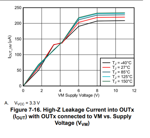
    The curve below shows the expected leakage into OUTx pin when OUTx is connected to VM. This leakage current is measured when OUTx is connected directly to VM or any other voltage. Adding some resistance between OUTx and external supply will of course bring the leakage down.

    That is, placing the bridge in high-Z mode and applying a voltage to an output pin will create a leakage current roughly equal to a 20-30k pulldown resistor no matter what VM is set to.

    Internally, there is a path to GND from OUTx. This is done by design for protection to prevent unexpected FET turn on due to transients when switching. 

    s this intended functionality or is there perhaps a flaw in my implementation?

    As I mentioned above, this is done by design. However, this leakage will not be present when not operation in Hi-Z mode or when load is connected to GND rather than VM.

    Can the leakage be reduced or avoided somehow?
    The best way to avoid it is to connect the load from OUTx to GND.

    Regards,

    Pablo Armet

  • I see, that makes sense. I do think that the datasheet should be more clear on that aspect, but otherwise I get it. It does note that no high-Z leakage is expected when the load is connected between the two outputs (as it normally is in my implementation). I'll try it when I'm back in the lab, but I have a deeper question about that. Assuming the load is a charged capacitor connected to the two output pins and the bridge is in high-Z mode, will the load not just end up with just a lower leakage? The output lower body diodes have a voltage drop of up to 1V. The way I see it the load would just end up hovering so that the lower voltage side is negative and the higher voltage side positive, with both voltages at the point where the positive side high-Z leakage current is equal to the negative side's body diode current leakage.Assuming a 2V load, this would probably be 20 uA or so. Is that correct?

    In my case that will not matter, the the voltage should be less than 1V meaning that the leakage should be small. But I prefer knowing how the IC works.

    Thanks

    Gabriel

  • Gabriel,

    Today is a US holiday.  Expect a response tomorrow.

    Regards,

    Ryan

  • Hi Gabriel,

    Let me clarify something first. The high leakage will be present when the FETs are High-Z and there is a voltage greater than 0V at the outputs. If you have a load, in this case a charged capacitor, connected across the each OUTx and a small voltage is generated at each of the outputs, there will be a small leakage when FETs are High-Z. However, if H-bridge is not High-Z (The HS FET of one half-bridge is ON and LS FET of the other half-bridge is ON), The high leakage will not be present.

    TO clarify, the load is connected across OUTx or the load is connected from OUTx to VM?

    When you took the leakage measurements, were the OUTx High-Z?

    Regards,

    Pablo Armet

  • Hello Gabriel,

    Any updates? I'm going to close this thread due to inactivity. Please reply back or post a new related question for further support.

    Regards,

    Pablo Armet