


Other Parts Discussed in Thread: DRV8353, CSD19532KTT
Hello Team,
We are a startup company named DeccanR Enterprises Pvt Ltd., from India. We are working on Automotive Application of building an EV two-wheeler 60V BLDC Motor controller development. After a thorough of research, we found the TI boards and using the TI DRV8353RS-EVM Evaluation board for controlling the BLDC motor.
Our specifications are as follows,
Motor: 60V BLDC motor (3 hall sensors are embedded)
Motor input: 19S5P LFP Battery (62 V nominal voltage)
Controller board: DRV8353RS-EVM
Software used: 2019b SIMULINK/MATLAB (SDK drivers)
It is a great experience to use TI board, as it provided a lot of details to build our own Application.
But we are having some doubts and need clarification from TI end regarding DRV8353RS-EVM board.
From the datasheet, this board is built for 100V and 20A (continuous 15A) but we require continuous 60V and 40A.
As per our understanding, we are assuming that
- FETs used in the DRV8353RS-EVM board can handle upto 100V and 100 Amps. Therefore, we are assuming that, the existing FETs are sufficient for our application. Please, correct me, if I am wrong.
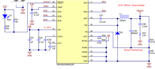
- We are assuming that, the DRV8353RS driver board has inbuilt ‘current sense limiting circuit’, that would restrict the current flow using a comparator circuit. This comparator circuit takes the reference current sense voltage signal and actual current sense voltage signal. Here, the reference signal controls the maximum current flow in the driver circuit.
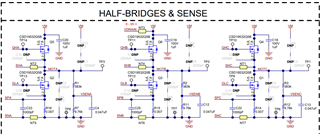
Therefore, we are assuming that, by replacing (R14, R15 and R16 shunt resistors) 7mΩ with a 3mΩ shunt resistor in ‘half bridge and sense circuit’ the driver actual current sense signal will be adjusted for delivering the 40A. Please, correct us, if we are wrong and appreciate your guidance in this regard.
We are assuming that there is a comparator inside the driver DRV8353 which has reference voltage set to some value.
So we think it takes the inputs from the SPA,SNA,SPB,SNB,SPC,SNC. And compare these difference outputs with the reference voltages
The below calculations are the some understandings
Calculation for Given specifications
Vmax = 20A * 7mΩ
V = I×R = 20A×0.007Ω = 0.14V
P = V×I = 0.14V×20A = 2.8W
Calculations for required specifications
Vmax = 40A * 3mΩ
V = I×R = 40A×0.003Ω = 0.12V
P = V×I = 0.12V×40A = 4.8W
We have following queries,
- Will you suggest any changes in existing PCB (DRV8353RS-EVM) to handle peak current of 40 Amps @ 60V DC?
- If not, will provide the guidance to build our own PCB for 40 Amps 60V DC motor controller PCB using the TI components?
- If not, will you please, suggest the board, that can meet our demands of 60VDC with 40-amp Peak current for BLDC/PMSM motor?
- From our observations, the peak current Amps for 60V BLDC motor seems pretty low. May I know, the DRV8353RS-EVM board delivers the 15 Amp (mentioned in datasheet) for the entire voltage range (9 to 95V)?
Best Regards,
DeccanR Team.
