This thread has been locked.

If you have a related question, please click the "Ask a related question" button in the top right corner. The newly created question will be automatically linked to this question.

BOOSTXL-DRV8323RS: Universal motor Control Lab

Part Number: BOOSTXL-DRV8323RS
Other Parts Discussed in Thread: TMS320F28379S, DRV8323

Hi,

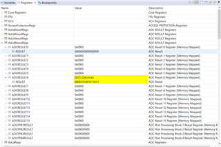
I am trying to run the Universal motor Control Lab code on a custom board(f28379s). I have ported the code as described in the lab guide, section 3.3. However, when I try to build Level 1 code, I can not read the supply voltage.

  • Hi Jagbir,

    Thank you for your question! Can you confirm that the BOOSTXL-DRV8323RS is powered up properly? How much voltage are you supplying to the VM input?

    Regards,

    Anthony Lodi

  • Hi Anthony,

    The DRV8323RS is on my custom board using TMS320F28379S as the MCU. I am supplying 48VDC to the Vm input. However, I have not connected the CMPSS as described in the f280025 and drv8323 example. Is it mandatory to use CMPSS Module for three shunt application. 


    Thanks

  • Hi Jagbir,

    I believe the CMPSS modules may be primarily used for overcurrent protection, so I don't think it would directly impact the ability of the motor to spin.

    You mention that when you build the level 1 code you cannot read the supply voltage. Did you only build the code? Or did you also run the code? The supply voltage is monitored when the code is running, since the code will periodically sample the ADC voltage for the supply voltage sensing. If you only build the code but don't run it, then this would result in the ADC voltage not being sensed. 

    Regards,

    Anthony Lodi

  • I am running the code and watching the expressions.

  • Hi Jagbir,

    Thanks for the clarification. Could you probe the voltage on the ADC pin that you are using as the input for the VBUS sensing? If you are seeing that the voltage is around 0V, then that would indicate that the issue is hardware related. If you are seeing the expected voltage on that pin based on the VBUS voltage, that would indicate that the issue is a result of the code not being configured properly.

    Also, when you pause the code after running it for some time, what line of code does it stop at? 

    Regards,

    Anthony Lodi

  • Hi Anthony,

    I was able to read the ADCIND1 after configuring the ADC D port. However, the measured value by the ADCIND1(37.27V) is incorrect. The correct value is 48V.  r

    The voltage measured at the pin is 2.16V, consistent with the resistor divider on 48V.

    Two questions:

    1. Why the measured value by ADC is incorrect

    2. What adc register stores the ADCIND1 value for f2839s devices. Is it ADCresult6 register.


  • Hi Jagbir,

    Glad to hear that you were able to read the ADCIND1 value! 

    1. The reason why the value displayed on the screen is incorrect is likely due to the fact that the resistor values for the resistor divider are different on your board compared to the BOOSTXL-DRV8323RS board. The code was written based on the values of the resistor divider. The ADC simply samples the voltage on the pin and converts it to a 12 bit number which is a representation of the voltage on the pin. The code would then multiply that value by the appropriate scale based on the resistor divider values on the PCB. This is what will need to be changed in the code based on your resistor divider value. You can calculate the scale factor by determining what voltage on VM would result in 3.3V on the ADC, and then the scaling factor would be that voltage divided by 4096 (number of samples possible for a 12bit adc.).

    2. It does appear that the ADCRESULT6 register is storing the ADCIND1 value. 

    Regards,

    Anthony Lodi