This thread has been locked.

If you have a related question, please click the "Ask a related question" button in the top right corner. The newly created question will be automatically linked to this question.

DRV8870: Reverse Current Protection Circuit Inquiry

Part Number: DRV8870

Hello,

My customer is considering using the DRV8870 for DC motor control.

Input power 24V, estimated current consumption is 1A.

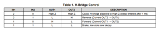
They assume that when controlling a DC motor (converting from CW to CCW or Pause), a reverse current will be generated due to the motor inductance.

Therefore, it is expected that the DRV8870 or source power needs a protection circuit for this. Are they right?

The EVM circuit does not have such a protection circuit. Is it okay if the user does not consider the reverse current?

Thank you.

JH

  • Hello JH,

    Therefore, it is expected that the DRV8870 or source power needs a protection circuit for this. Are they right?

    This app-note provides guidance for protecting against back-emf induced overvoltage on the supply pins. In short summary, driving in BRAKE mode will minimize the risk of overvoltage due to the current path being restricted to the bottom LS FETs and motor.

    Regards,

    Pablo Armet

  • Hi Pablo,

    Thanks for your reply.

    The customer has further questions.

    1. Does the brake mode eliminate the need for a separate external circuit (Freewheeling Diode)? Is Coast mode the same?

    2. Does it just add a brake between direction turns(using 100% duty)? (ex CW --> Brake --> CCW)

    3. How long should the Brake (OFF Time) be maintained when controlling the speed by PWM method? Do you have any calculation method?

    Regards,

    JH

  • Hi JH,

    1. Does the brake mode eliminate the need for a separate external circuit (Freewheeling Diode)? Is Coast mode the same?

    It helps to use BRAKE mode to minimize back-emf induced voltage spikes but it can still occur if the devices is set to sleep mode while motor is spinning. When device is set to sleep mode, the FETs are disabled. Freewheeling coast (all FETs disabled) is the same as coasting.

    2. Does it just add a brake between direction turns(using 100% duty)? (ex CW --> Brake --> CCW)

    Not for direction change at 100% duty cycle. It only goes to brake mode and PWMing at non 100% duty cycle with periods of current decay (current recirculation). However, if you are driving at 100% duty cycle and current regulation is enabled, the driver will switch outputs causing the H-bridge to go into BRAKE decay.

    3. How long should the Brake (OFF Time) be maintained when controlling the speed by PWM method? Do you have any calculation method?

    at minimum 400ns to ensure proper operation.

    Regards,

    Pablo Armet

  • Hi Pablo,

    The customer has some questions.

    1. They judge that a protection circuit is needed against the Back-EMF effect. Could you please let us know if there is an external protection circuit you recommend?

    2. They are considering two designs:

        CASE#1 : Reverse Current Protect by adding a schottky diode

        CASE#2 : Back-EMF Voltage Clamping by adding TVS diode

       Please let us know if there is a valid design in either case.

    Thank you.

    JH

  • Shin,

    There is an app-note that shows various methods for back-emf protection. 

    Your proposed designs are acceptable. 

    Regards,

    Pablo Armet