This thread has been locked.

If you have a related question, please click the "Ask a related question" button in the top right corner. The newly created question will be automatically linked to this question.

BOOSTXL-DRV8323RH: DRV8323RH fault after enable it

Part Number: BOOSTXL-DRV8323RH
Other Parts Discussed in Thread: DRV8323, MSP430FR2355, DRV832X, MSP430F5529, CSD19506KTT, BOOSTXL-DRV8323RS, TIDA-010056

Hi team,

My customer need assistance.

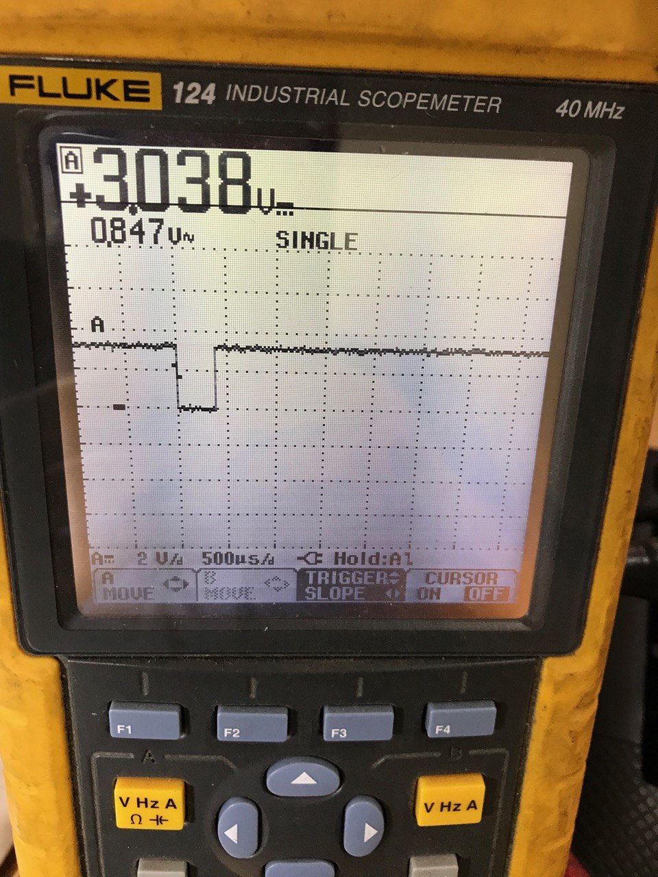
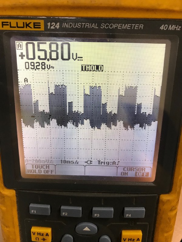
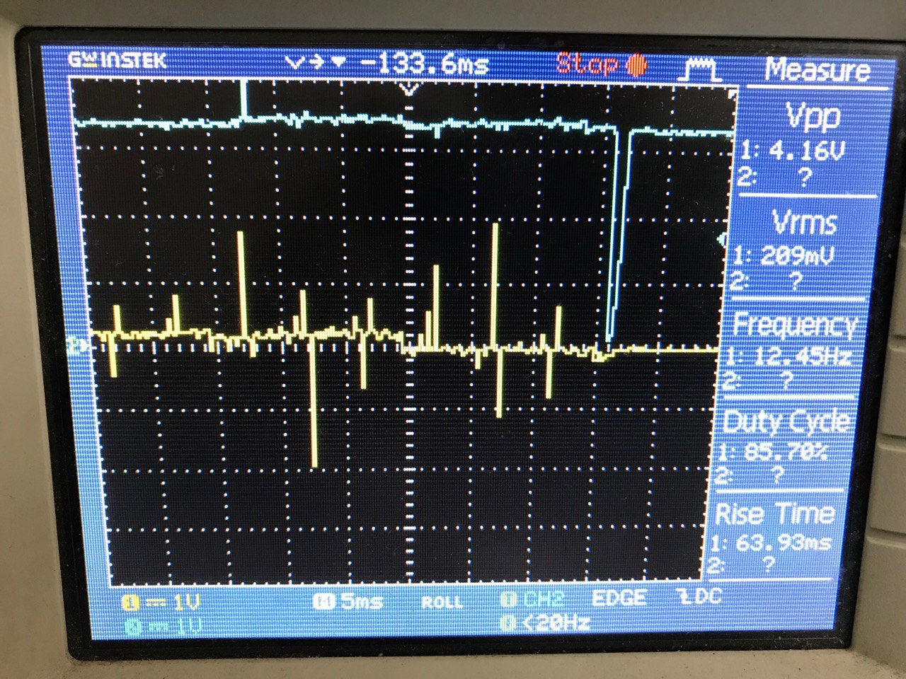
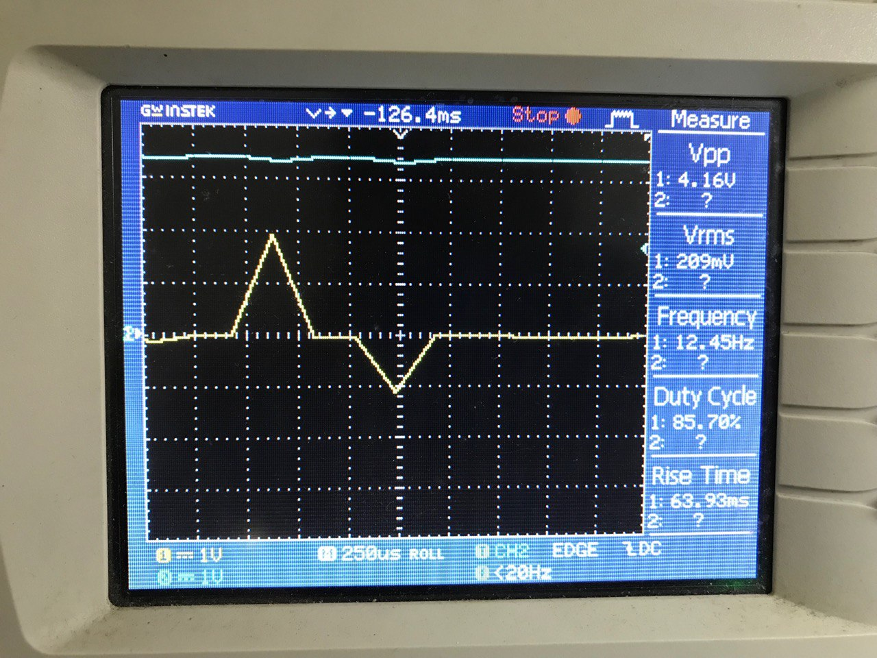
I have designed a PCB similar to BOOSXL_DRV8323RH, using DRV-8323RH to control a BLDC motor. I have used MSP430FR2355 to control it. During the debugging process, the fault pin of DRV8323 produced an active low pulse that triggered an interrupt on the MSP430 and initiated an interrupt service routine (ISR) to report the fault.
I have checked, but I am unable to identify the location of the error. Please help me resolve it
MDNN schematic.pdf

  • Hi Chong,

    We have a FAQ on debugging faults with hardware device variants that maybe helpful (Link).

    In the schematic I noticed that capacitor C2 is a 4.7 μF capacitor, we recommend that this capacitor be greater than or equal to 10 μF.

    Does the fault occur when motor is starting/stopping, spinning, or being hand-spun?

    Thank you,

    Joshua

  • Hi Joshua,

    I got the response from customer:
    Thank you for your response. My issue is that after I turn on the drv8323 by enabling the enable pin, the error appears immediately. When I measure the GHA, GHB, GHC pins, they have a higher voltage than VM, while the SHA, SHB, SHC pins have the same voltage as VM. I don't know why this is happening because even when I replace the drv8323 with a different one, it still has the same error.
    The Mode, Cal, Gain, Idriver, and Vds pins as shown in the diagram are connected to the microcontroller. How
    should I configure these pins in the microcontroller?

  • Hi Chong,

    1. Could the customer go though the FAQ on debugging faults with hardware device variants? This will help to quickly identify what is casing the fault to be raised.
    2. Can the customer operate the external MOSFETs despite the fault? If they can, could the customer provide me a waveform of GHA, SHA, INHA, INLA? 
    3. Could the customer provide a waveform of the VM, VCP, VDS, and nFault pins at startup with a falling edge trigger on the nFault pin?

    The Mode, Cal, Gain, Idriver, and Vds pins as shown in the diagram are connected to the microcontroller. How
    should I configure these pins in the microcontroller?

    For the hardware variants of the DRV832x devices, these pins are configured though pullup and pull down resistors. The microcontroller can be used as the source for the logic low or logic high for these pull up/pull down resistors, but they will need to use the correct value resistor if the pin setting they want requires it.

    Best regards,

    Joshua  

  • Hi Joshua,

    I got the response from customer:
    I disconnected the Idrive, Vds, and Gain pins of the drv8323rh from the microcontroller, but when I supplied power, the voltage on these pins was 3.3V in Hi-Z state instead of about 1.65V as specified in the datasheet. When I connected the idrive pin through a 75k resistor to GND, the voltage on the idrive pin dropped close to 0V, while the datasheet specifies it should be around 1.1V. I don't know where this issue comes from, it could be due to my manual soldering error, but I have tried several drv8323rh chips and still have the same issue. I would appreciate any advice from you.

    Thank you.

  • Hi Chong,

    1. Could the customer provide a graphic showing where on the board and what type of probe they used to measure the voltages of the pins?

    2. Was there anything connected to the pins when they where in a Hi-Z state?

    Thank you,

    Joshua

  • Hi Joshua,

    I got the response from customer:
    drv8323rh error.docx
    Thanks

  • Hi Chong,

    1. Just to make sure that I understand VCC correctly, which voltage source is this referring to?
    2. Could the customer re-do the last two measurements in the document but use a DC voltage measurement instead?
    3. Could the customer provide a waveform capture of the DVDD pin?

    Thank you,

    Joshua

  • Hi Joshua,

    I got the response from customer:
    drv8323 error.docx
    Thank you very much.

  • Hi Chong, 

    Our team is out of office today for a US holiday, but will be back in office next week. 

    Please anticipate a delayed response until then, but we'll get back to you with a comment on your questions at soonest convenience. 

    Best Regards, 
    Andrew 

  • Hi Chong,

    I will need some time to consult with my team about this issue. I will aim to get a response to you by the end of the week at the latest.

    Best Regards,

    Joshua

  • Hi Chong,

    Could the customer use an oscilloscope to perform the voltage measurements. We would like the customer to use the oscilloscope so that we can see the voltage of the pin, currently with the scopemeter we cannot see the voltage with reference to ground only the peak-to-peak voltage.

    Thank you,

    Joshua

  • Hi Joshua,

    I got the response from customer:
    I think I have fixed the drive issue, which may have been caused by poor soldering of components before. However, now when I enable the motor, it rotates a few turns and then stops completely. The motor is in an unloaded state, so the current is not too high.
    When I debug the program, it runs to MOTOR_RUN, which means it is in a closed-loop control state. So what could be causing my motor to stop?
    Thank you.

  • Hi Chong,

    When the motor stops spinning does the nfault pin go low?

    Could the customer provide an oscilloscope capture of the GHx, GLx, SHx, and SLx pins? If the nfault pin is going low when the motor stops spinning please have a trigger for when the nfault pin goes low for the capture.

    Thank you,

    Joshua

  • Hi Joshua,

    I got the response from customer:
    When the motor stops spinning, the nfault pin does not go low, but I cannot capture the nfault strigger when the motor is spinning because when I measure the nfault pin, the motor is not spinning and nfault pin does not go low. Whenever I enable the driver, there will be a pulse down to about 400us of the nfault pin as shown in the figure, so it takes 3s for the motor to start spinning after recovery. Video 1 is the oscilloscope capture of GHx and SHx pins, video 2 is the oscilloscope capture of GLx and SLx pins from when the driver is enabled to when the motor stops spining.
    Thank you.

  • Hi Chong,

    1. What is the PWM mode of the device during this operation? 
    2. Once the motor stops spinning does the DRV8323 still try to drive the gates, are there still signals coming from the MCU to the INHx/INLx pins?
    3. What are the VM and VCP voltages when the motor is spinning?

    Thank you,

    Joshua

  • Hi Joshua,

    I got the response from customer:
    I am using the 6x PWM mode to control a BLDC motor. After debugging, I found that the motor went into closed-loop mode and reported a motor stall error. After 3 seconds of recovery, the motor continued to spin and reported the motor stall error again. The on/off process continued like this. My code was modified from the "DRV8323_MSP430F5529_Trapezoidal_Sensorless_BLDC" code and replaced with MSP430fr2355.
    Thank you.

    You can see in the video that when the trapezoidal signal ends, the motor stops and the voltage on pin GHx rises to 22V. After a 3s recovery, the trapezoidal signal returns and the motor continues to spin, and when it stops, the voltage on GHx rises to 22V again. This process continues like this.
  • Hi Chong,

    If VM is still 24V, like was shown previously, then the VCP might be not functioning correctly since it should be keeping GHx ~11 volts over VM. 

    1. Just to confirm, is the VM voltage still 24 volts when this problem is occurring?

    2. What is the VCP voltage when this problem is occurring?

    3. Is it possible for the customer to provide a capture of each phase node voltage in a single capture over a period of time so that we can analyze them? 

    Thank you,

    Joshua

  • Hi Joshua,

    I got the response from customer:
    VM is always 24V, VCP voltage is 36V. The picture is waveform of a phase.

  • Hi Chong,

    I will bring this problem up in a team meeting this week, I will get back to you with a response by this Friday at the latest.

    Thank you,

    Joshua

  • Hi Joshua,

    I got the response from customer:
    I have a question, is there any issue with my schematic besides replacing C2 with a capacitor over 10uF? My application is to control a BLDC motor with a maximum voltage of 46V (11 cells) and a power of around 1kW.
    Thank you.

  • Hi Chong,

    1. Is there another oscilloscope that the customer can use, I was seeing that the GHx voltage was 22V in the video but it should be equal to VCP?

    2. What is the switching frequency of that the customer is using?

    Everything on the schematic besides capacitor C2 looks ok. 

    Best regards,

    Joshua

  • Hi Joshua,

    I got the response from customer:
    The other oscilloscope also shows the same waveform. The clock frequency for Timer is 24MHz, and the PWM frequency is 24kHz. At first, I used an SMCLK frequency of 24MHz for ADC, but it did not work correctly. Then I had to use a MODCLK frequency for ADC.
    I don't know if there's an issue with my common ground design or not, when I use a small motor, the program stops at closed loop control and restarts, but when I use a larger motor, the program only stops at open loop control and turns off the gate driver.
    Should I separate the MCU from the gate driver and MOSFETs like the BOOSTXL board?
    Thank you.

  • Hi Chong,

    To see if the common ground is causing issues the customer can look at noise on the analog signals, if the noise is high then a split ground design could help fix the issue.

    I will reach out internally about the motor stopping issue. I will get a response to you as soon as I receive information.

    Thank you,

    Joshua

  • Hi Chong,

    For the both cases, is the program within the MCU causing the motor to stop or is the gate driver experiencing a fault causing the motor to stop, I am a little confused here?

    Best regards,

    Joshua

  • Hi Joshua,

    I don't know exactly where the error is, but it is likely in the gate driver. I have tested it on two motors, one with small power and one with large power (1kW), and both are unloaded. Their reactions are different, with the small motor being able to run to
    closed loop control and then stopping and repeating (possibly not reaching the BEMF threshold), and the large motor stopping after a few cycles of open loop control. Images and videos are attached in the file.
    Thanks.

    8688.Waveform.docx

  • Hi Chong,

    Could the customer provide a capture of the current waveform from any of the phases when the motor is spinning?

    Best regards,

    Joshua

  • Hi Joshua,

    I got the response from customer:
    waveform (1).docx
    Thanks.

  • Hi Chong,

    We believe that the motors stopping while running maybe caused by the sensorless feedback and commutation not being configured correctly in the code. We recommend that the customer view our video titled Stages of motor control as it maybe helpful to them.

    Best regards,

    Joshua

  • Hi Joshua,

    I got the response from customer:
    Why does the driver always report an error in the first cycle when I enable the gate driver?
    Thanks

  • Hi Chong,

    Finding which fault is being raised on hardware devices can require a lot of back and forth between us and the customer. To speed up this process we created the FAQ on debugging faults with hardware device variants so that customers could more easily and quickly find the fault and have recommendations of what could be causing the fault.

    If the customer could provide me which fault they believe is occurring, why they think it is that fault, and what they have tried already to solve it I could offer more support.

    If the nFault pin is going High after the device is enabled and then goes low after a short time, then this is likely a charge pump under voltage fault and in this scenario is usually not a problem.

    Best regards,

    Joshua

  • Hi Joshua,

    I got the response from customer:
    large motor error.docx

    Thank you.
  • Hi Chong, 

    Josh is currently out of office but will be back tomorrow. Please anticipate a delayed response. 

    Best Regards, 
    Andrew 

  • Hi Joshua,

    I got the response from customer:
    After checking the fault, I believe that the error occurred in Vsense overcurrent. The yellow line represents SLx, and the green line represents nFAULT. What should I do to resolve this issue?


    Thanks.
    Regards

  • Hi Joshua,

    I got the response from customer:
    I am using the MOSFET CSD19506KTT with Rsense=2mOhm. According to the calculations,
    IDRIVE=Hi-Z, VDS=Hi-Z .
    If I set IDRIVE=Hi-Z and VDS=Hi-Z, the driver reports an error and the motor does not rotate at all. Therefore, I connected IDRIVE=75k tied to GND, then the motor had a slight jerk and reported an error. Then, I connected IDRIVE=18k tied to GND, and the motor rotated a few rounds before reporting the same error. Are there any other parameters that I can adjust?
    Thanks.

  • Hi Chong,

    Because the customer is using a input voltage above 50% the absolute maximum value we recommend that the customer move to a different device like the DRV8353Rx. Using a device with a absolute max greater than 2x the batteries nominal voltage may help them with driving the motors, especially the larger motor. 

    Best,

    Joshua

  • Hi Joshua,

    I got the response from customer:
    Your answer is not acceptable. I clearly stated from the beginning that my application is to control a 1kW BLDC motor with an 11-cell battery. And you mentioned that there is no issue with my schematic. Furthermore, even when I used a 24V voltage, the problem still persists. Moreover, I have used the BOOSTXL-DRV8323RS for my application without any issues during no-load operation. Therefore, there is no reason why the DRV8323RH would not be suitable for this application. Otherwise, it suggests that your product has unstable quality and does not meet the specifications stated in the datasheet.
    Thanks

  • Hi Chong,

    Could the customer provide a capture showing the Vsense_OCP fault event? This capture will need to nFAULT, SPx, and SNx with single-ended probes (or SPx-SNx with a differential probe) wtih a trigger on an nFAULT falling edge.

    Thank you,

    Joshua

  • Hi Joshua,

    I got the response from customer:
    I only have a two-channel oscilloscope with single-ended probes, and according to my schematic, SNx is connected to GND. In the image above, the yellow waveform represents SPx, and the blue waveform represents nFault. Currently, I am referring to TIDA-010056, where DRV8350RS integrates a 350mA buck regulator, and this supply provides power for both the driver and the controller. Please explain why this power supply is used for the driver instead of VM, and whether it is too small to also supply the controller?
    Thanks.

  • Hi Chong,

    Please explain why this power supply is used for the driver instead of VM

    The 15V buck output is used to supply the gate driver to "ensure that the quiescent current consumption is minimum compared to powering up the VM pin with DC input" (see section 2.4.3 of the TIDA-010056 Design Guide). The DRV835x devices have the ability to support split supplies to the VM and VDRAIN pins, see DRV835x Split Supply Power Topology for more information.

    whether it is too small to also supply the controller?

    Maybe I misunderstand your question but the DRV8350RS internal buck can supply the controller. On the TIDA-010056 an LDO is used on the board to step down the 15V from the internal buck down to 3.3V which is used to power the MCU.

    Best,

    Joshua

  • Hi Joshua,

    I got the response from customer:
    Please help me check if there is any issue with this schematic.1_V3.pdf
    Thanks.

  • Hi Chong,

    Please allow my a couple of days to look over the schematic, I'll get you a response by next Wednesday at the latest.

    Best,

    Joshua

  • Hi Chong,

    1. The capacitor connected to the VCP pin should be connected between VDRAIN and VCP not VM and VCP. This is especially true since VM and VDRAIN are not using the same voltage source.
    2. For the pullup/pulldown resistors on VDS and IDRIVE, these are fine as options but is is not recommended for both the pullup and pulldown resistors to be populated at the same time.
    3. If the pullup resistor for IDRIVE is used alone will result in (450 mA) of peak source gate current, this may be a bit excessive since this setting will result in a rise time of 44ns . We recommend targeting a 100-300 ns rise time. 
    4. For the SPI resistors, it is not recommended for the pullup/pulldown resistors to be populated if a SPI device is being used (other than the 3.3V pullup on the SDO pin)

    I could not check the VDC input as I could not find it on the board, but as long as this voltage is within specifications and there is enough capacitance, like with VM, there should not be a problem.

    Regards,

    Joshua

  • Hi Joshua,

    I got the response from customer:
    Thank you for your response. I understand the configuration of the VDS and IDRIVE pins. In my schematic, they are merely to indicate the SPI options and hardware variant, as well as the changes in pull-up or pull-down resistors depending on the MOSFET variant. In this application, I use one supply for VM and VDRAIN (I forgot to update VDC to VM in the schematic). I will test this new circuit next week and will further discuss with you once I have the results.
    Thanks.

  • Hi Joshua,

    I got the response from customer:
    I am testing a new PCB with DRV8350RS. After reading data from the driver via SPI, the driver is reporting all errors as shown in the image, even though I haven't enabled it yet.

  • Hi Chong,

    When the DRV8350RS's enable pin is low the device is placed into sleep mode. In sleep mode the devices SPI Bus is disabled and therefore the fault register cannot be read, please see section 8.4.1.1 of the datasheet for more information.

    I would suggest enabling the device, wait for the maximum twake time (1ms), and then preform any SPI read or writes.

    Regards,

    Joshua

  • Hi Joshua,

    I got the response from customer:
    Currently, after I enable the gate driver, the fault pin immediately goes low. At that point, in the fault interrupt routine, the commands to read the error register values via SPI are not functioning, so it fails to detect any errors and continues executing the program until it detects that the motor is not spinning and reports a motor stall error. In the TIDA-010056 documentation, there is a mistake in the schematic regarding the connection of SDI and SDO pins, which also confused me. If I had initially connected the SPI incorrectly (which is now connected correctly) and the fault ISR is not working properly, would it damage the DRV8350RS?

  • Hi Chong, 

    If I had initially connected the SPI incorrectly (which is now connected correctly) and the fault ISR is not working properly, would it damage the DRV8350RS?

    Swapping of the SDO and SDI pins should not cause any damage to the device but to be sure the device is not damaged, the customer can swap in a good device to check.

    Currently, after I enable the gate driver, the fault pin immediately goes low.

    To check that the SPI commands are not working, the customer can probe the SPI signals to see what is being sent between the devices. If they would like a reference of a working SPI signal the customer can probe the SPI signals on our EVM. If they can determine the fault being reported, please have them look though our debug guides: Quick Guide to Debugging Common Issues in BLDC motor drivers and Debugging faults with Hardware variant devices.

    Regards,

    Joshua

  • Hi Joshua,

    I got the response from customer:
    I have discovered a very high startup current by measuring the voltage at the IA_IDC pin, which could be the cause of the driver reporting an error. Currently, I have replaced the DRV8350RS with DRV8350RH and the device is still operating at 24V, and when the motor voltage reaches 44V, it briefly jerks and then the driver shuts off completely. I have tried increasing VDS to 75 kΩ ± 5% tied to DVDD and changing the resistor values connected to IDRIVE, but with no success. Do you have any suggestions on how to reduce the startup current?

    Thanks.

  • Hi Chong,

    Just to be sure, is the device reporting an overcurrent error? If the microcontroller cannot read the error in time, please have the customer measure the SPI signals to determine the fault being reported.

    Regards,

    Joshua

  • Hi Joshua,

    I got the response from customer:
    Currently, I have another issue with the SPI communication between MSP430FR2355 and DRV8350RS. Please help me check if there is any issue with my code.SPI.docx