Other Parts Discussed in Thread: CSD88584Q5DC, CSD87333Q3D
I used a translator. Please excuse me.
Hi.
I am inquiring about the DRV8306 motor driver.
I am inquiring about the DRV8306 motor driver.
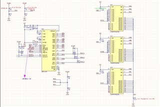
I attached the data sheet and circuit diagram of the BLDC motor that I am using.
When operating the motor, the current value rises from the maximum duty ratio to 3A, and the motor is severely heated.
1. When the PWM frequency is 100 kHz, there is no difference in speed or current value from 50% duty ratio or higher.
2. If the PWM frequency is raised to 200 kHz, there is a difference in speed and current value, but the motor is severely heated.
The current goes up to 3A when the duty ratio is 90%.
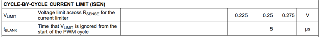
3. R sense(R64) shunt resistor was connected 0.075 ohms according to the formula below because the current value was too high when 0.007 ohms was connected the same as the EVM board.
0.225V(V Limit) / 3A = 0.075
0.225V(V Limit) / 3A = 0.075
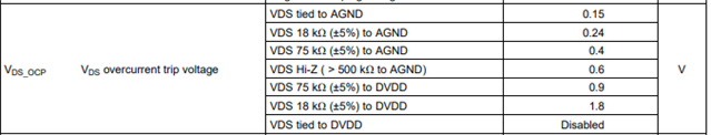
4. The I Drive setting is set to 75k ohm to DVDD, which I think is appropriate, while raising the low value.
When the I Drive setting is low, the nFault pin goes low and the motor does not turn.
When the I Drive setting is low, the nFault pin goes low and the motor does not turn.
5. When the motor is rotating quickly at a high duty ratio, if an external force is applied to stop it, a current of more than 5A is consumed.
Shouldn't the current value be limited to 3A by the R sense value?
Shouldn't the current value be limited to 3A by the R sense value?
The hole sensor and OUT pin are connected in the same way as page 13 of the datasheet.
When I asked FAULHABER about the motor, they said that it should be used at a high frequency of 100 kHz or higher.
Therefore, we are testing at frequencies above 100 kHz, and when I checked the datasheet of CSD88584Q5DC, I found that the switching frequency was up to 50 kHz.
Is the current value high and heat generation severe because it is outside the maximum frequency of the FET?
I wonder if there will be no problem if I change FET to CSD87333Q3D.
Thank you.

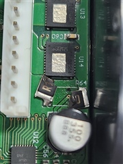 The Rsense resistor broke during the motor loop test.