This thread has been locked.

If you have a related question, please click the "Ask a related question" button in the top right corner. The newly created question will be automatically linked to this question.

DRV8244S-Q1LEVM: SPI control using Arduino

Part Number: DRV8244S-Q1LEVM

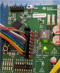
Hi I need support in setting up the board. I have connected the board with Arduino pins

GND - GND

PIN 13 - SCLK

PIN 12 - SDO

PIN 11 - SDI

PIN 10 - nSCS

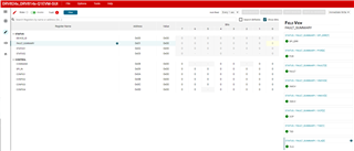
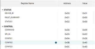
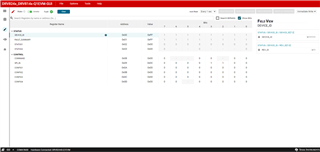
Register Map looks like this:
Can you share a sample Arduino code to drive the motor ? Thanks.

- Ankit

  • Hey Ankit,

    See the device datasheet for basic steps on control of the driver:  https://www.ti.com/lit/ds/symlink/drv8244-q1.pdf This should be able to get you to spinning the motor.

    Unfortunately we do not have any sample code for this device beyond the DRV824X_DRV814XQ1EVM Software.  We don't have an Arduino library for this part yet, and it is so new that I don't think any other company has built a library for it yet.  You can look to see if any other company has made a library for it such as Pololu, Adafruit, Sparkfun, etc. or build your own library similar to another library.

    You may instead want to use the Hardware version of this device, see https://www.ti.com/tool/DRV8244H-Q1EVM.  

    Best,

    Jacob 

  • Hello Jacob, thanks for sharing the datasheet. that helps understand the register map. Using that Info I tried to write a register value but fail.

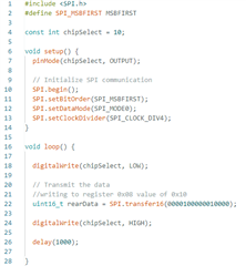
    My code looks like this

    There is no faults but why is the register value not changing ? Thanks.

    -Ankit

  • Hey Ankit,

    In your transfer16 function you need to set the number type to binary.  The way you have it written it is trying to transfer the number 1,000,000,010,000.  Put a B in front of it to change it to binary per this tutorial:  HOW TO WRITE BINARY AND HEXADECIMAL NUMBERS IN ARDUINO.  

    Do you have access to a Saleae Logic Analyzer or and Oscilloscope or any other way to verify that your commands are being sent properly?

    I also believe the SPI_MODE needs to be SPI_MODE1.  And you should set the CS pin to HIGH right after you initialize it, so that for the transaction it goes LOW-TRANSACTION-HIGH, the way I see it in your code it is undetermined-TRANSACTION-HIGH.  

    Best,

    Jacob

  • Hello Jacob,

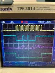
    I updated the script as per the above comments. My signal looks like this on the oscilloscope

    Yellow - SCLK

    Blue - SDI

    Pink - SDO

    Green - SCS

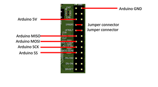
    Connections looks like this

    If the signal looks good, what sequence the registers be updated ? I am updating 

    1) Command register 0x08 to value 0x10 (to enable SPI) 

    delay 1 millisecond

    2) SPI register 0x09 to value 0x06 (drive forward)

    Do we need to set value to any other register or leave the rest to default ? Thanks.

    - Ankit

  • Hey Ankit,

    See the below/attached code, I have tested it with DRV8244S-Q1EVM.  DRV8244S-Q1-Arduino-SPI.ino

    I jumped over all the pins from the EVM to the Arduino Uno except the IPROPI  pin.  Make sure you use the RIGHT side of the J4 header (driver side), as the left side is connected to the EVM microcontroller and not the driver. 

    #include <SPI.h>
    
    // SPI Protocol
    #define SPI_ADDRESS_MASK   0x3F00        // Mask for SPI register address bits
    #define SPI_ADDRESS_POS    8             // Position for SPI register address bits
    #define SPI_DATA_MASK      0x00FF        // Mask for SPI register data bits
    #define SPI_DATA_POS       0             // Position for SPI register data bits
    #define SPI_RW_BIT_MASK    0x4000        // Mask for SPI register read write indication bit
    
    // Arduino CLK = PIN 13
    // Arduino SDI (MISO) = PIN 12
    // Arduino SDO (MOSI) = PIN 11
    #define CS_PIN 10
    #define NSLEEP_PIN 9
    #define NFAULT_PIN 8
    #define IN2_PIN 6                     
    #define IN1_PIN 7
    #define DRVOFF_PIN 5
    
    // Brushed DC Motor Connected between OUT1 and OUT2 on DRV8244S-Q1EVM
    // All jumpers on J4 removed except IPROPI
    
    void setup() {
      pinMode(NSLEEP_PIN, OUTPUT);  digitalWrite(NSLEEP_PIN,  1);
      pinMode(CS_PIN, OUTPUT);      digitalWrite(CS_PIN, 1);
      pinMode(IN2_PIN, OUTPUT);     digitalWrite(IN2_PIN, 0);
      pinMode(IN1_PIN, OUTPUT);     digitalWrite(IN1_PIN, 0);
      pinMode(NFAULT_PIN, OUTPUT);  digitalWrite(NFAULT_PIN, 0);
      pinMode(DRVOFF_PIN, OUTPUT);  digitalWrite(DRVOFF_PIN, 0);
    
      delay(5);
    
      SPI.begin();         // initialize the SPI library
      SPI.setDataMode(SPI_MODE1);
    
      write8(0x08, 0b10000000); // Send CLR_FLT command
      delay(5);
    
      // Enter PWM Mode
      write8(0x0C, 0b01000011); // set S_MODE = 0b11 for PWM mode
      digitalWrite(DRVOFF_PIN, 0);
    
    }
    
    void loop() {
    
      // Accelerate
      for (int i = 0; i < 255; i++)
      {
        analogWrite(IN2_PIN, i);
        delay(2);
      }
      delay(1000);
    
      // Decelerate
      for (int i = 255; i >0; i--)
      {
        analogWrite(IN2_PIN, i);
        delay(2);
      }
      delay(500);
    
    }
    
    void write8(uint8_t reg, uint8_t value) {
    
      // This SPI function is used to write the set device configurations and operating
      // parameters of the device.
      // Register format |R/W|A5|A4|A3|A2|A1|A0|*|D7|D6|D5|D4|D3|D2|D1|D0|
      // Ax is address bit, Dx is data bits and R/W is read write bit.
      // For write R/W bit should 0.
    
      volatile uint16_t reg_value = 0; // Variable for the combined register and data info
      reg_value |= ((reg << SPI_ADDRESS_POS) & SPI_ADDRESS_MASK);         // Adding register address value
      reg_value |= ((value << SPI_DATA_POS) & SPI_DATA_MASK);             // Adding data value
    
      digitalWrite(CS_PIN, LOW);
    
      SPI.transfer((uint8_t)((reg_value>>8) & 0xFF));
      SPI.transfer((uint8_t)(reg_value & 0xFF));
    
      digitalWrite(CS_PIN, HIGH);
    }
    

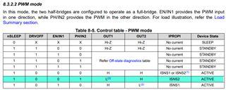
    My code uses this line of PWM control mode:

    Best,

    Jacob

  • Hi Jacob, 

    Thanks for sharing this. It is working for me now. I was connecting the pins on the wrong side of header. Maybe it can be worth mentioning in the User Guide. I have a couple follow up questions.

    1) Can we use GUI to monitor the registers while we are using SPI ? I am having a tough time in getting the board connected in the cloud GUI. Are there certain steps one should follow ? (like connecting a few 0 ohm register in order for the USB connection to work ?) 
    2) I see that you are passing IN1 and IN2 signal using digital pins, can we control them using SPI and register maps ? so that we don't need 2 additional wire connections.

    3) How do I read the bridge current ?

    Regards,
    -Ankit

  • Hey Ankit, yeah good point, I'll work on getting that updated! 

    1) Can we use GUI to monitor the registers while we are using SPI ? I am having a tough time in getting the board connected in the cloud GUI. Are there certain steps one should follow ? (like connecting a few 0 ohm register in order for the USB connection to work ?) 

    Generally no, you would have to set the Arduino-side pins as high impedance (Hi-Z) (set them as an INPUT) whenever the GUI is reading from the device, and the SPI jumpers would have to be placed back onto the EVM.  Part of the EVM code for connecting to the device reads some SPI registers, so if the EVM jumpers for the SPI pins isn't connected it won't be able to connect to the GUI.

    One workaround I've used in the past is to get the EVM to the state you want using the GUI, then save/write down the register address+values from the Register Map page.  Use the Arduino code to just write all of those values to the device.  Ex. write the Address and Value directly to the Arduino. 

    2) I see that you are passing IN1 and IN2 signal using digital pins, can we control them using SPI and register maps ? so that we don't need 2 additional wire connections.

    Correct, that's exactly the case.  The only limitation is that it is difficult to implement PWM using the SPI control - you can do it, but your frequency will be limited by how quickly and consistently you can send SPI commands to toggle the bit. 

    3) How do I read the bridge current ?

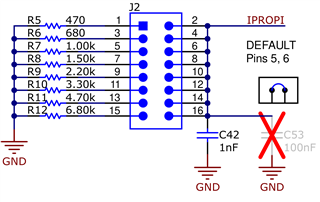
    Connect the IPROPI pin to an Analog Input pin on your microcontroller.  Note that you need the R_IPROPI resistor still attached, so I recommend leaving the shunt jumper on J4 for IPROPI and just hooking a wire onto the jumper to sense it.  

    Best,

    Jacob

  • Hello ,

    Can we have the bridge current over SPI ? Idea is to have only SPI connection between the 2 boards. Is the DRV8244S-Q1EVM capable of doing that ? I dont see IPROPI on any register bits.

    Regards, 

    Ankit

  • Hey Ankit,

    Unfortunately not, this device doesn't have IPROPI in a SPI register.  

    Best,

    Jacob

  • Hello Jacob,

    What is the mapping of IPROPI pin ? how do I know the bridge current based on Analog voltage ? Thanks.

    Kind Regards, 

    Ankit Verma

  • Hey Ankit,

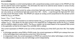
    See 8.3.3.2 IPROPI in the device datasheet:

    AIPROPI is 4570 or 4750 depending on the package:

    So if the driver was running at 1A (I_hs + I_LS = 1A), then IPROPI = 1A/4750A/A  = (1/4750) A.

    Then use the IPROPI resistor you select on the EVM - let's say it's at 1kΩ.  V =1000Ω*(1/4750)A = 0.210V on IPROPI pin. 

    Best,

    Jacob