Other Parts Discussed in Thread: CSD88584Q5DC, DRV8306,
Hi,
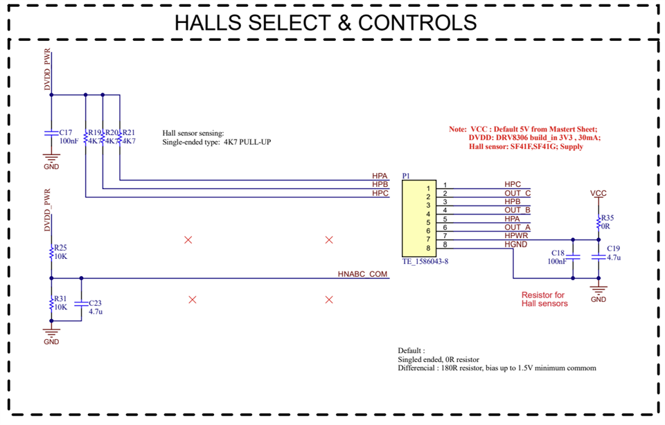
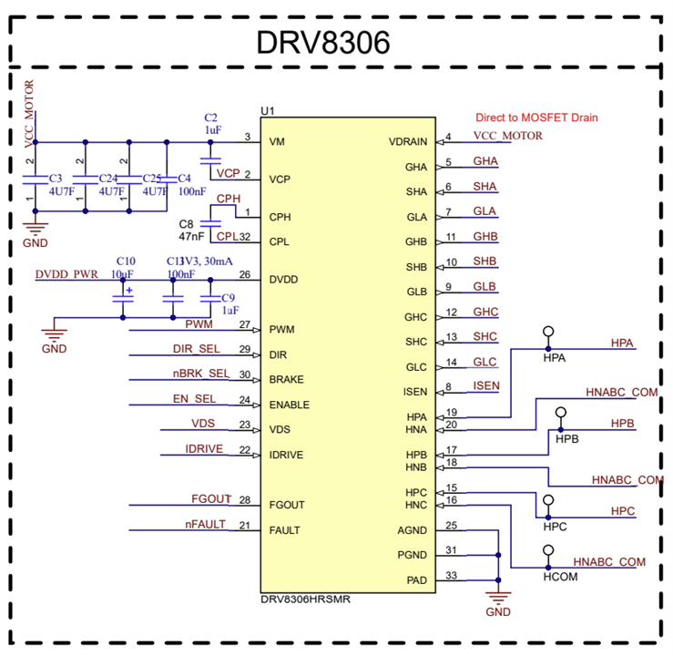
My company makes a range of products which use BLDC motors. The control board for this range uses a DRV8306 coupled with 3 x CSD88584Q5DC to drive each motor, with each board driving a total of 2 motors (side A & B). This drive circuit is essentially the same as the DRV8306EVM evaluation board, so for this question please use that as a design reference.
After much work/testing/compliance (and help from this forum!) - this product range was released to the market 2 years ago. Since then we have sold hundreds of units around the world, and they have proven extremely reliable - with no faults directly related to the drive circuitry. Nice :)
However recently we received 4 x control boards back from a new customer. These units worked for several weeks, then would no longer drive the motors. We had only supplied them with 8 units total, so this was very strange indeed.
On checking the boards I found 3 which show the same issue on both sides A and B.
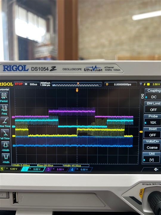
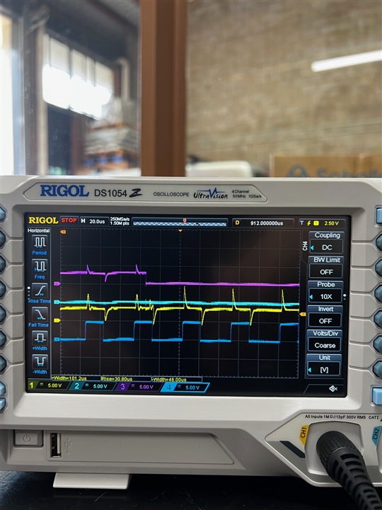
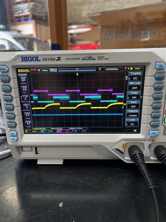
After start-up, our system is normally in brake mode - so GHx are all OFF, and GLx are all ON (10V wrt SHx).
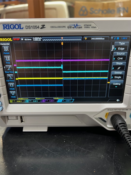
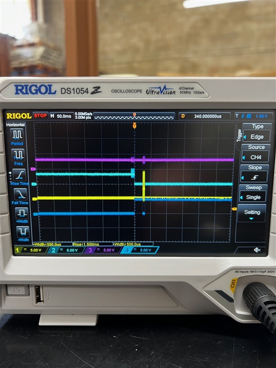
On these units though, at startup GLx is 0V and GHx is showing 24V wrt GND (note: VM = 24V in our system). 24V is also seen on all outputs / SHx i.e. there is no differential between GHx and SHx. This state does not change either when you attempt to activate the motors. Again, this is the same on 3 boards, both sides A and B - so 6 x drive circuits in total.
On the 4th unit, one side is still working. On the other side though, it will power up into brake mode as normal (GHx are all OFF, and GLx are all ON). However, if you try to activate the motor, it will not start and the circuit will then go into the state mentioned above - GLx = 0V and GHx/SHx = 24V / VM
I just saw the interesting FAQ by Alicia Rosenberger re: Why do SHx and GHx Float? This seems to explain what I am seeing i.e. GHx is essentially shorted to SHx. If so that would mean both the low-side and high-side FETs are not on - however that should not be the case!
So onto my questions - does the above sound likely (both high and low FETs are off) and if so - does that mean these FETs have failed in some way? and if so, what are the most likely causes of this type of failure?
OR could it be an issue with the DRV8306 failing to turn the FETs on? I have checked the key inputs to the DRV (nBRAKE etc) and all seemed normal there. The last thing to note is this circuit is over-specified for our application - our motors are 24VDC and run below 3A (and less than 1A in the product(s) which saw these failures) - so considerably under the ratings for the CSD88584Q5DC.
Any input would be great appreciated and please let me know if I can provide more data to assist. Thank you!