Tool/software:
For the continuation of the thread "DRV8711: Assistance with DRV8711 DC Motor Driver Issues":
Could you kindly provide suggestions or modifications needed to make the motor work with the IRLS4030TRLPBF MOSFETs.
This thread has been locked.
If you have a related question, please click the "Ask a related question" button in the top right corner. The newly created question will be automatically linked to this question.
Tool/software:
For the continuation of the thread "DRV8711: Assistance with DRV8711 DC Motor Driver Issues":
Could you kindly provide suggestions or modifications needed to make the motor work with the IRLS4030TRLPBF MOSFETs.
Hello,
Although the current ratings are suitable for the load, it looks like the gate to source voltage, VGS, is larger for IRLS4030TRLPBF and will require a higher gate voltage to turn on. I suggest measuring the gate to source voltage and make sure it's large enough to bias both FETs.
Best,
David
Hi sir,
The gate-to-source voltage of the AUIRF540ZSTRL is ±20V, while the gate-to-source voltage of the IRLS4030TRLPBF is ±16V.
When we attempt to operate the system through the DRV8711 in PWM mode, it does not work. However, it runs successfully in open-loop with a direct power supply. Kindly provide suggestions or guidance on the necessary implementation to make the IRLS4030TRLPBF MOSFET work in PWM mode.
Hi Dhivya,
The gate-to-source voltage of the AUIRF540ZSTRL is ±20V, while the gate-to-source voltage of the IRLS4030TRLPBF is ±16V.
These are the absolute maximum specifications for these FETs, not the operating voltage. These don't matter. What matters are the VGS threshold and the Qg specifications. The VGS threshold of the 4030 is 2.5 V max vs. 4 V for the 540. Both are lower than what the DRV8711 can provide. This would be a non-issue.
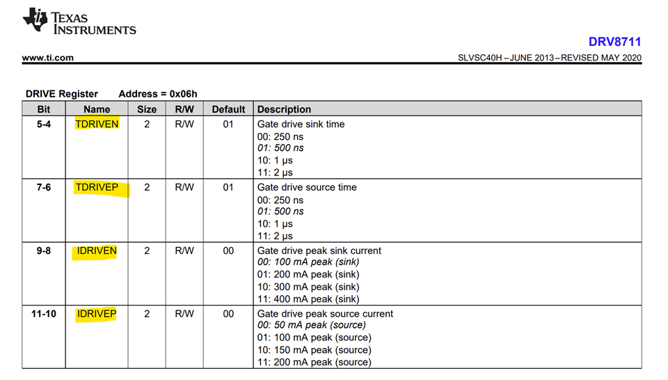
The Qg of the IRLS4030TRLPBF is higher than the AUIRF540ZSTRL. This means it requires higher current drive setting. Please refer to section 8.2.2.3 Support External FETs in the datasheet, page-35.
A potential solution could be to increase IDRIVEP and IDRIVEN settings and if needed also TDRIVEP and TDRIVEN settings. Thanks.

Regards, Murugavel
Hi sir,
Thanks for your reply!
DRIVE Register: 0x650F
Please verify the above value of the register.
Hi Dhivya,
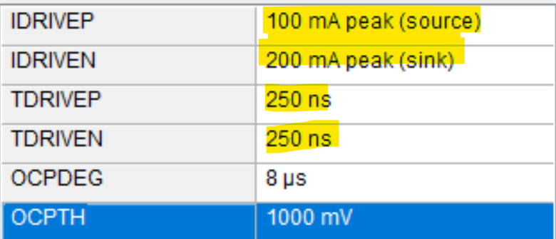
DRIVE Register: 0x650F
This translates to lowest TDRIVEP and N as following values for IDRIVEx settings.

Like I mentioned previously "Please refer to section 8.2.2.3 Support External FETs in the datasheet, page-35." use the formulae in this section to calculate the required settings for your MOSFETs.
I think you can try setting TDRIVEP and N to 1 μs and increase IDRIVEP and N. For example, try setting 0x6AAF and if that does not resolve try 0x6FAF and if not 0x6FFF.
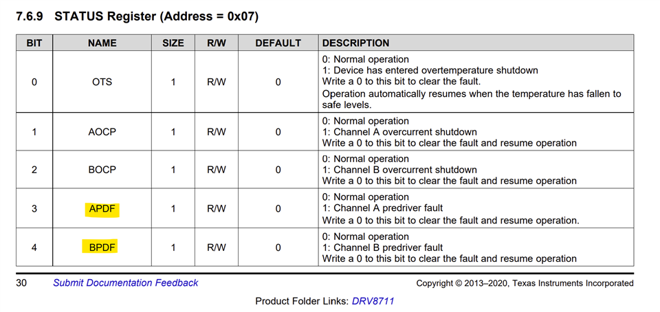
While the motor is not running with the 0x650F setting can you read the STATUS register and see if APDF or BPDF bits were set? Please share the STATUS register value read for each setting 0x650F, 0x6AAF, 0x6FAF and 0x6FFF. Thanks.

Regards, Murugavel
Dear Sir,
I tried different configurations based on your suggestions, but the value of the status register bits value (0) didn't change.
Hi Dhivya,
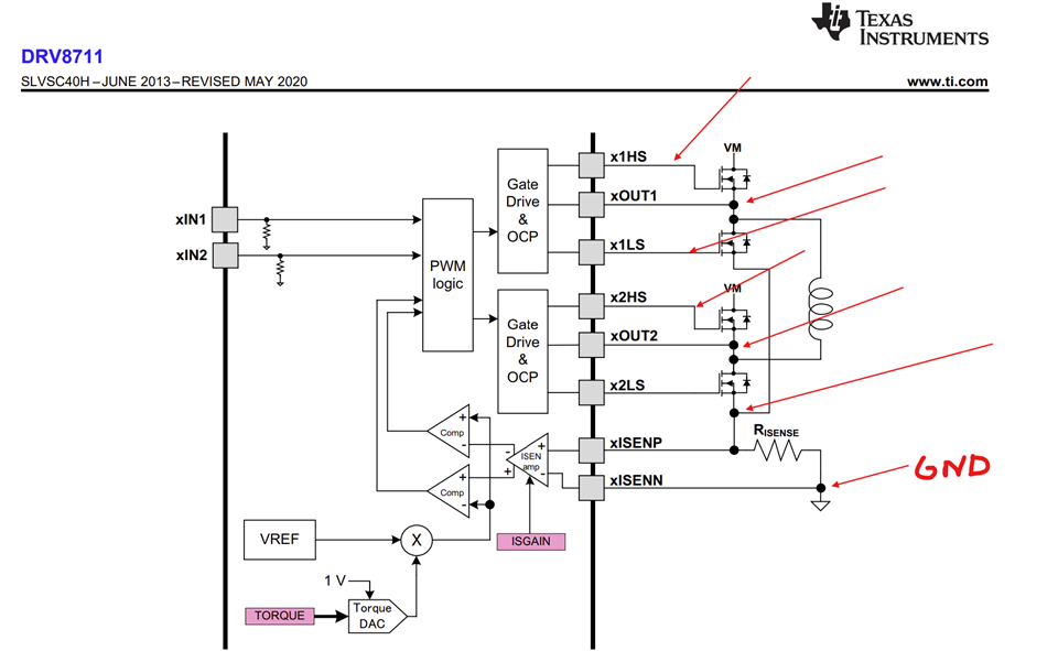
If APDF or BPDF bits were not set in the STATUS register means the gate drive was normal. Did increasing IDRIVEP and IDRIVEN solved the output issue? Can you please provide oscilloscope captures for the following nodes while the device is actively driving - see below. Thank you.

Regards, Murugavel
hello sir,
we are in need of your support for BDC motor, after setting the full torque register value as 0XFF still the full scale current is not driven by driver to motor
and our rsense register value is also 0.01ohm.
Hi Dhivya,
It's difficult to tell from the scope captures provide which signal is which. Can you please add labels to these images? If following in order from Murugavels suggested nodes of capture, it looks like x2HS is the only gate that is seeing any voltage. Also please include input control sequence. Is the motor trying to be driven in forward or reverse (with or without PWM)?
Best,
David