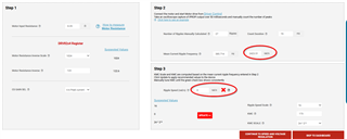
This thread has been locked.

If you have a related question, please click the "Ask a related question" button in the top right corner. The newly created question will be automatically linked to this question.

DRV8214: RC_OUT discrepancies with IPROPI pin

Part Number: DRV8214


Tool/software:

Dear Texas Instruments Support Team,

I am writing to report an issue we are experiencing with the DRV8214EVM board. 
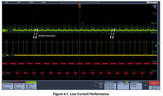
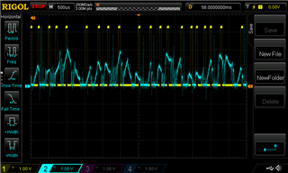
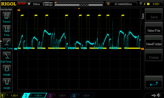
Attached, please find oscilloscope captures that illustrate the issue.
During our analysis of the RC_OUT signal (yellow signal), we have noticed discrepancies when comparing it with the IPROPI pin (blue signal), which supplies the board’s output current.
Specifically, the peaks (and thus the ripple measurements) often do not coincide, which is hindering our ability to implement the driver.

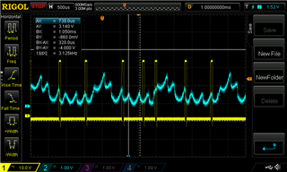
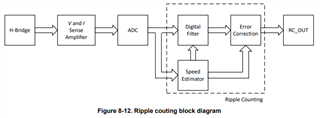
  Could you please provide clarification on how the RC_OUT output is calculated from the board’s output current? Understanding this in detail will help us better integrate and troubleshoot the system. Thank you in advance for your assistance.
I look forward to your prompt response. Regards
Fabio B
  • Hi Fabio,

    There is a detailed description of how the ripple counting algorithm is implemented provided in the datasheet in section 8.3.6 Ripple Counting.

    Also a common challenge we see when implementing ripple counting can occur when using low average currents. The difficulty with low current is the SNR is reduced and can cause the current ripple to become distorted and the noise is mistaken for a ripple leading to double pulses to occur. 

    Please see the following app note for a common work around with this and more common challenges and workarounds. 

    Best,

    David

  • Hi David,

    Thanks for your answer.

    After studying your application note and after make minus adjustment we still have a ripple count that does not follow the actual ripples.

    As you can see in the images below, the yellow RC signal is not uniform and sometimes does not match the ripples of the blue IPROPI signal.

    How can we improve the system to get the right match between RC signal and IPROPI signal?

    Thanks and Best.

    Fabio B

  • Hi Fabio,

    The motor current doesn't seem to be uniform. Is the motor spinning, and if so, is there a load attached or a gearbox on the motor? 

    Best,

    David

  • Hi David,

    The image above was taken on a rotating motor.

    The motor is connected to a 64:1 gearbox, with no load, just a very light optical encoder wheel.

    Best.

    Fabio

  • Hi Fabio,

    Try removing the gearbox when tuning the motor.

    It's also important to measure the resistance of the motor correctly. If the motor resistance isn't provided by the datasheet, I would suggest following suggestion 2 from the GUI suggestions for measuring motor resistance. Be sure to use an inline multimeter to measure the current for higher accuracy. 

    The two circled values should be close to matching after tuning and a green check mark will signal a successful tuning. 

    Best,

    David