MCF8316A: MCF8316A: All three phase outputs (OUTA/B/C) show same PWM waveform — no phase shift or commutation

Part Number: MCF8316A
Other Parts Discussed in Thread: MCF8316D, MOTORSTUDIO, MCF8316C-Q1

Hello TI Team,

I’m working with the MCF8316A and observing an issue where all three phase outputs (OUTA, OUTB, and OUTC) show identical waveforms (square waves with no 120° phase shift). The motor does not rotate.

Hardware setup:

  • Motor: BLDC, 2-pole, rated for 24 V

  • Supply: 24 V DC

  • Driver: MCF8316A

  • Controller: STM32H755ZI Nucleo board (I²C used for configuration and register reads)

  • PWM_SPEED pin connected to PB0 of STM32 (providing ~15 kHz PWM duty for speed input)

  • DIR and BRAKE pins controlled by MCU GPIOs

  • OUTA/B/C probed at MCF8316A output pins (not MCU pins)

Symptoms:

  • When I probe OUTA/B/C, I get three identical square signals (no phase shift).

  • The ALGORITHM_STATE register reads MOTOR_MPET_KE_MEASURE(0x0014).

Despite that, the motor doesn’t rotate and output waveforms remain identical.

What I have tried:

  • Confirmed supply voltage stable at 24 V, SPEED_MODE in PIN_CONFIG register is set to 01b.
  • Checked the GATE_DRIVER_FAULT_STATUS, there are no faults.
  • Checked the CONTROLLER_FAULT_STATUS, there are no faults.
  • Tried changing ALIGN_ANGLE to 120°, but no change in output waveform.

Questions:

  1. Why are all three phase outputs (OUTA/B/C) producing identical waveforms?

  2. Does ALIGN_ANGLE influence output waveform phases, or is phase shift only active once the motor starts rotating?

  3. Do I need to explicitly trigger a commutation start command after alignment?

Any insights or debug steps to confirm if the MCF8316A is actively commutating would be greatly appreciated.

Thanks & Regards,
Aniruddha P


  • Hi Aniruddha 

    Thanks for explaining the additional details.

    When the device is in ALIGN mode due to startup or Align Brake, all phases will have the same alignment.

    I also want to recommend updating the design to MCF8316C or MCF8316D for new designs.

    Please refer to the errata list (+) [FAQ] Production device information - Motor drivers forum - Motor drivers - TI E2E support forums

    Can you share the schematics?

    Thanks and Best regards

    Venkatadri S

  • Hi Aniruddha,

    Any update for me?

    Thanks and Best regards

    Venkatadri S

  • Subject:  MCF8316C-Q1: Motor runs no-load but stops under small load — CURRENT_LOOP_SATURATION & CONTROLLER_FAULT in MotorStudio

    Hello Venkatadri,
    I am using the MCF8316C-Q1 DVK evaluation kit with the MotorStudio (Three Phase GUI) to drive a FL45BLW23 BLDC motor.
    The motor starts and runs smoothly under no-load conditions up to the rated speed. However, when I apply even a small mechanical load, the motor immediately loses torque and stops. The MotorStudio GUI reports the following faults:
          CONTROLLER_FAULT
          CURRENT_LOOP_SATURATION
    Sometimes also 
          ABN_BEMF or MTR_LCK

    I have attached a screenshot from MotorStudio showing the configuration and faults.

    Setup Details:

    Driver IC:   MCF8316C-Q1 (EVM/DVK)
    Motor:   FL45BLW23 (2-pole BLDC motor)
    Supply Voltage:   24.5 V DC
    Rated Current:   6 A
    Rated Speed:   746 Hz
    Control Mode:   Speed mode (Sensorless)
    PWM Frequency:   50 kHz
    Startup Method:   Slow First Cycle
    Startup Time:   1 s
    Application:   Pump (selected in GUI)

    Motor Parameters (from SmartTune / GUI):

         Phase Resistance (R): 0.4000 Ω
         Phase Inductance (L): 0.1550 mH
         BEMF Constant: 13.000 mV/Hz
         ISD State: ISD_COMPLETE
         Speed Feedback: ~3409 Hz (no load)

    Behavior Observed:

       Motor runs fine up to the target speed under no load.
       As soon as a small load is applied, the motor torque collapses and the GUI shows CURRENT_LOOP_SATURATION fault.
       Increasing the speed reference or I2C speed command makes the motor fault faster.
       Supply voltage (VM) stays near 24 V — minimal voltage droop observed.
       Increasing current limit or re-running SmartTune does not improve load handling.

    Steps Already Tried:

       Re-ran SmartTune multiple times (both manual and auto modes).
       Verified wiring and phase order.
       Adjusted BEMF constant slightly around the datasheet value.
       Increased ILIMIT and closed-loop current limit.
       Tested at lower PWM frequency (no improvement).
       Verified that the power supply is rated for 6 A continuous.

    Questions for TI:

    What are the common root causes for CURRENT_LOOP_SATURATION when the motor can spin no-load but fails under small load on MCF8316C-Q1?

    Does this fault indicate voltage saturation, current-limit saturation, or control-loop windup?

    Which registers or parameters (e.g., current controller Kp/Ki, ILIMIT, voltage modulation settings) should I review or tune to prevent this?

    Are there any recommended tuning guidelines or example configs for low-inductance motors like the FL45BLW23?

    Would adjusting the speed loop bandwidth or Iq reference limit help in maintaining torque under load?

    Attachments Available (on request):

       MotorStudio configuration screenshot (included)
       Fault logs from MotorStudio
       FL45BLW23 motor datasheet

    Thank you,
    Anirudh


    0880.FL45BLW23-24V-6045A-EN 1.pdf

  • Hi Aniruddha,

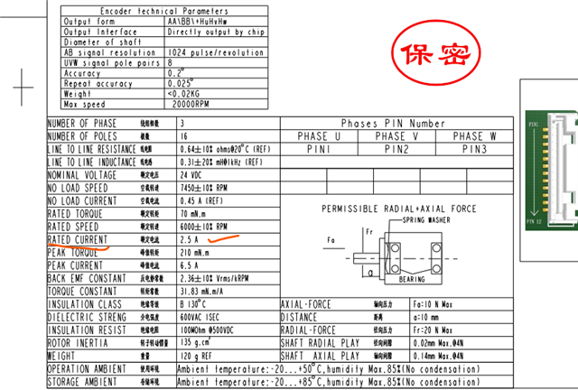
    I looked at the motor datasheet and I see that the current to be entered is less than 2.5A, which is mentioned as the rated current. The 6.5A may be the stall current.

    The current loop saturation flags indicate that the device cannot increase current further because the motor has already reached its maximum speed for applied voltage.

    This is because, for 6A input, the device divides the entered rated current into a few steps to analyze mechanical properties. When there is no load, even for a smaller current step, the motor would have reached its maximum speed.

    We have explained such scenarios in the FAQ and application note.

    Thanks and Best regards

    Venkatadri S