Hi,
I am using the DRV8432EVM in Mode 4 to switch 12v across an actuator from a PWM signal generated by an arduino. This will eventually be used in a force control PID loop.
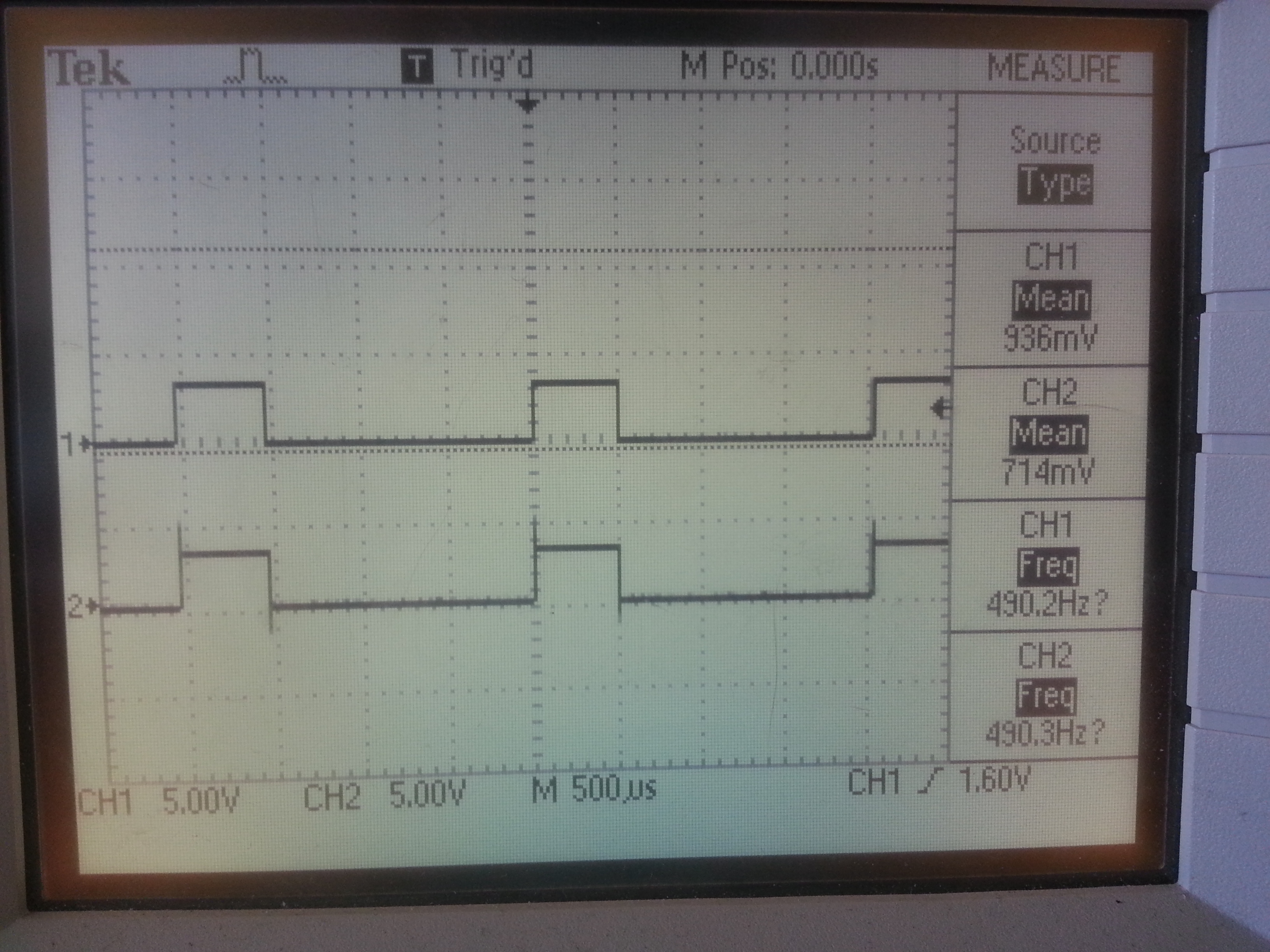
I am currently applying a 0%, 25%, 50%, 75% and 100% pwm duty cycle into PWM A and C inputs to view the outputs. With this in mode 4, i would expect to see the voltage across the OUT A and B average 0v when 50% pwm is put through PWM A. Unfortunately, i do not see this, instead getting the same PWM signal as the output across OUTA and B, only amplified to 12v.
Can you offer any advice to ensure when i apply a PWM signal (eg. 25%, the motors go foward, 50% they stop and 75% they reverse.) to perform the switching. I assumed the complimentary pwm input across the PWM B when in mode 4 would do what i described above.
Thanks,
Vaughan