This thread has been locked.

If you have a related question, please click the "Ask a related question" button in the top right corner. The newly created question will be automatically linked to this question.

DRV8711 Parameter Settings

Other Parts Discussed in Thread: DRV8711EVM, DRV8711

Hi at all!

I am trying to control a steppermotor with a resolution of 400 full steps per revolution (0.9°) in indexer mode with 256 microsteps.

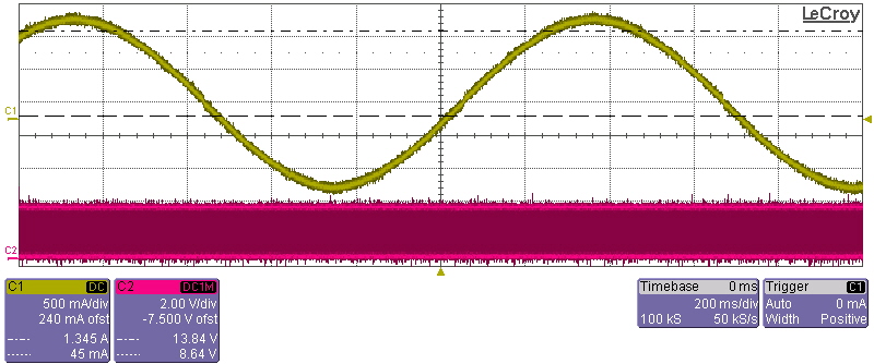
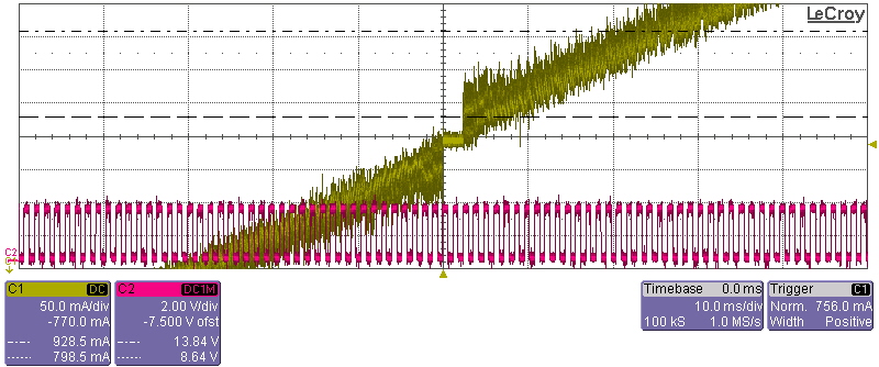
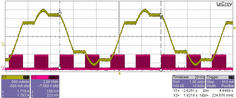
The problem is, that the motors movement isn't smooth. The motor is cogging each time a full step is reached.

Currently I am using following parameters:

- Dead Time 400ns (CTRL Register)

- Off Time 500ns (OFF Register)

- Blanking Time 2us (BLANK Register)

- Fast Decay mode at all times (DECAY Register)

I am using the DRV8711EVM developement board and a stepper motor with 1.33A/phase, 4.2mH/phase, 2.1Ohms/phase and a voltage of 24V over the h-bridges.

Can somebody tell me which parameters I have to change to get a smooth movement of the motor.

Kind regards,

Michael

  • Hi Michael

    I will recommend you use "auto-mix decay all the time" and also below settings.

    Dead Time: whatever

    Off Time 5 to 20us

    Blanking Time 1 to 2.5us

    And for other setting please refer to datasheet.

    This should give you a good sine wave current without cogging.

    Thanks.

    Wilson Zuo


  • Hi Wilson!

    Thanks for your answer.

    I did smoe experiments with the values you suggested and some tests with register settings around the boundaries you have mentioned.

    I have attached two screenshots of the measured current waveform for following register settings:

    - 1.33A full-sclae current, 256 microsteps
    - 25us OFF time
    - 4us blank time
    - 12.5us decay time, auto mixed decay
    - 300mA LS drive, 150mA HS drive, 500ns LS and HS drive time

    - step frequency is 800Hz

    The screenshot pic1 shows a full period of the current waveform (yellow graph - current waveform; purple graph - signal at step input). The screenshot pic2 is a zoom at the zero crossing of the current. There is no continuous gradient of the current which results in a cogging movement of the motor. The duration of the zero current zone is nearly 2.5ms.

    screenshot pic1


    screenshot pic2


    Do you have any idea how to get a better performance of the current waveform during zero crossing?

    Thanks.

    Michael

  • Hi Michael

    It looks not bad. To lower the zero crossing distortion, you can enable the ABT bit to enable the adaptive blanking time function. I think that will help.

    Thanks

    Wilson Zuo

  • Hi Wilson!

    Thanks for the hint with the adaptive blanking time function. However it doesn't increase the performance.

    Now I have another question. I am using a stepper motor with 0.9° resolution (400 fullsteps for 360° rotation). So the DRV8711 should drive a current similar to a sinewave through the coils of the motor for each fullstep. Is this correct?

    The following screenshot shows the current with 500ms delay after each fullstep (divided by 256 microsteps). The DRV8711 needs four fullsteps to generate a full periode of a sinwave.


    So maybe the reason of the cogging isn't the zero crossing but a faulty functionality of the driver?

    Thanks and regards,

    Michael

  • Hi Michael,

    I think your understanding is slightly off. A bipolar stepper motor will actually move 4 full steps in a sine wave.

    To understand this. Think of a stepper motor in full step mode. There are two phases, A and B.

    The combinations are...

    A   B

    1   1

    1   0

    0   0

    0   1

    For each of these combinations the stepper motors moves a step. Microstepping holds the motor between these positions in an attempt to make these transistions smoother.

    So your waveform makes perfect sense! Wilson can correct me if anything is explained incorrectly

    Are you wondering why the sine wave is not stopping at 71% after each pause?

  • Hi Nick!

    Thanks for correcting my misunderstanding.

    I asume that current level at the end of a fullstep is depending on the electrical angle.

    I think that the cogging torque of the stepper motor is too high and so there is no smooth movement possible - neither by using 256 micro steps.

    Do you have any idea to compansate the effect of the motors cogging torque?

    Thanks,

    Michael

  • It is possible the mechanical build of the motor is a limitation of your movement.

    The signal you posted is a fairly good looking sine wave.

    The only way to possibly improve on this is to furthur clean up the current regulation ripple (you may be pretty close to as far you can go though).

    Wilson had some good recommendations, auto mixed decay, minimize blanking time to speed up the TON response and reduce TOFF to decrease the amount of time current decays. Down side is that you are increasing your switching losses as you increase the speed at which the current regulation responds.

    Try:

    Auto Mixed Decay

    TBLANK = 1us

    TOFF = 5-15us

  • Hello,

    I want to add something. I am trying to drive my stepper motor in 256-Microstepping mode with 125 KHz indexer pulse. That means the period of my indexer is 8us and that is also means 4us high 4 us low.


    As you mentioned before i calculated my decay setup values but here is a point which confusing me. i got sinusiadal wave form in 32Khz with 10us Toff but now with 125 KHz indexer my indexer period is 8us itself.


    Should i decrease that Toff time? Because i think  (2*Tblank+2*Decay Time) or Toff Time should be smaller than my indexer's period.

    Can you enlighten me? Thank you.

  • Hi Erhan

    If the real performance of the motor running is meet your requirement, you don't have to do the decrease.

    The current regulation is already span over the steps in your case. Since you are already in an very fast running state of the stepper motor equivalent to about 500Hz(125k/256) step input at Full step, we should be more care about whether the motor is running smooth at this condition. When ever you slow down or stop, the 1/256 micro step resolution is still there.

    Also the internal index is still working correctly in this PWM frequency < input frequency condition. You don't have to warry about the motor will running unwanted steps.

    Best regards,

  • i have no problems in slow speeds.

    But when my speed rises there is a problem occurs. supply current of motor decreases %80 and shape of current wave getting sharper. Here is the video with drv8711EVM   in 256microstepping and 32000 Pulse per second. with 2000 accel rate. with automixed decay-alltime. i changed every values but couldnt succed.

  • Hi Erhan

    I can't see your video. But I think I understood your problem. Giving a motor, the current regulation will be lost and no longer a sine wave no matter how the decay parameters were tuned when the speed is increasing to some value. The inductance of the motor and BEMF just limit the current increasing rate even there is no PWM at all. This is a natural thing in all stepper motor and drivers.

    Increasing the VM voltage or change to a low inductance motor will help to improve the problem (Maintaining the sine wave current at higher speed). 

    Usually this is not an issue that must be solved if the motor haven't lost much torque to cause a full step missing during operation.

    Best regards,

  • I agree with Wilson.  The sine shape is lost because current can't reach the peak level at that fast of a step rate.  Higher VM or lower L will help.

    Best regards,
    RE

  • thank you all. i solved my problem with connecting motor in parallel style and increase driving voltage to 48V. both of them helped me.

    Thank you.