This thread has been locked.

If you have a related question, please click the "Ask a related question" button in the top right corner. The newly created question will be automatically linked to this question.

DRV8818 Issue at Mixed decay operation

Other Parts Discussed in Thread: DRV8818EVM, DRV8818

Hi

I operate motor by DRV8818EVM in the following condition.
- 3000pps
- 24V
- 1.5A
- 1/2 step

In this condition, in only Mixed decay case, motor can not be operated.
I would like to get advice about cause of this issue.

Please see the following waveform.
Figure 1 is Slow decay.
Figure 2 is Fast decay.
Figure 3 is Mixed decay.

DRV8818.pptx

Best regards,
Shimizu

  • Hi Shimizu-san,

    Can you provide some additional information?

    1) A schematic of the DRV8818 and surrounding components.
    2) A scope capture of the current, the output voltages, and the HOMEn pin
    3) A scope capture of the current in both windings
  • Hi Rick-san,

    Thank you for your support.
    I answer as the following for your question.


    >1) A schematic of the DRV8818 and surrounding components.
    Ans) Schematic is EVM. But I changed R value for Toff.
    R5 and R7 is 37.5k-ohm.
    Other parts is same default EVM.

    >2) A scope capture of the current, the output voltages, and the HOMEn pin
    Ans) I took the this picture as attached file(Figure 1 - 4)

    DRV8818_Answer_of_Q2.pptx

    >3) A scope capture of the current in both windings
    Ans) I'm sorry. I don't have two current probe.
    I took picture each windings as attached file(Figure 5 - 8) only mixed decay.

    DRV8818_Answer_of_Q3.pptx

    Thanks
    Shimizu

  • Hi Shimizu-san,

    Thank you for the information. The HOMEn pin is asserting at incorrect times. This indicates a fault is being detected (overcurrent, thermal shutdown, undervoltage).

    Can you add the AOUT2 voltage in slides 1 and 2 of Q3 and zoom in further?
    Can you add the BOUT2 voltage in slides 3 and 4 of Q3 and zoom in further?
    Also, what is the VREF voltage?

    Is this behavior seen on multiple boards? If not, is it possible the device has been damaged?
  • Hi Rick-san,

    Thank you for your support.
    I answer as below.

    >Can you add the AOUT2 voltage in slides 1 and 2 of Q3 and zoom in further?
    Ans) Please see the attached file(Fugire 1 - 4)

    DRV8818_Answer_of_Q3-2.pptx

    >Can you add the BOUT2 voltage in slides 3 and 4 of Q3 and zoom in further?
    Ans) Please see the attached file(Fugire 5 - 6)

    >Also, what is the VREF voltage?
    Ans) 1.2V

    >Is this behavior seen on multiple boards? If not, is it possible the device has been damaged?
    Ans)It is minority. it is possible the device has been damaged.
    I changed IC from EVM's default IC to customer IC.
    Now I analysis.

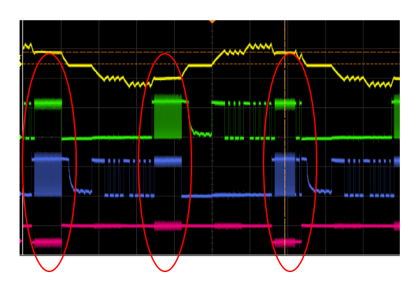
    I think fast decay's waveform is incorrect, too.
    Please see the first post attached file.
    and the following picture is fast decay.
    Is red circle operation correct?

    Best regards,
    Shimizu

  • Hi Shimizu-san,

    The operation in the circle does not appear to be correct.

    Please provide the lot trace code for the customer device.

    Thank you.
  • Hi Rick-san,

    Thank you for your support.
    I understand this IC is incorrect operation.

    Lot trace code is "4ATC" "CH57".

    Just for information.
    We have promoted the procedure of TI analysis.

    Thanks,
    Shimizu
  • Hi Shimizu-san,

    Do you have an update on the device status?

    Thank you.

  • Hi Rick-san,

     Thank you for care.

     We have proceeded with the procedure for analysis through TI Japan sales.

    Thanks,

    Shimizu