This thread has been locked.

If you have a related question, please click the "Ask a related question" button in the top right corner. The newly created question will be automatically linked to this question.

SN754410: H-Bridge weird behavior

Part Number: SN754410

Hello, 

I'm using the SN754410 to drive an actuator. I set it up on a breadboard and interfaced it with a micro-controller.

It work perfectly, until I changed the SN754410 to another breadboard, after that I've noticed weird behavior on the H-bridge.

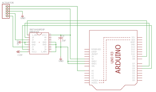
Below is the schematic of my connections:
 

The weird behavior revolves around pin 1A (pin 2). I measured the voltage on 1A with a voltmeter and this are my observations:

  • When no voltage is applied on Vcc2:
    • 1A goes HIGH and LOW, HIGH with a value of 5V and LOW with a value of 0.20V
  • When there is voltage supplied on Vcc2(12V):
  • 1A goes HIGH with a voltage of 5V  but LOW stays around 2.10V and thus the output 1Y never goes low


I also measured pin 2A to compare it to 1A; 2A goes to 0V when LOW whether there is voltage or not at Vcc2.

These are some of the things I have tried to fix the problem:

  • I tried changing the SN754410 for another. I tried 4 others and all of them had the same problem. They were all brand new.
  • I tried using pull down resistors for the INPUTS of the SN754410 (EN, 1A, 2A). In this case 1A would go LOW but HIGH was about 1.2V
  • I have tried changing the micro-controller, nothing.
  • I have tried changing it to another breadboard, still nothing

I don't understand why it suddenly stopped working, I've been looking around but haven't found anything that could help me solve this problem.

Here is the datasheet for the SN754410: http://www.exploringarduino.com/wp-content/uploads/2013/06/SN754410-datasheet.pdf

I am looking for any help on what I could be doing wrong or what is wrong, I am happy to answer any questions to clarify anything!

Thank You!


  • Hi Jorge,

    Please note the most current SN754410 datasheet can be found at www.ti.com/.../sn754410.pdf

    What is different about the two breadboards? If you have a working breadboard, measure or scope the signals around the device and compare them against the non-working breadboard.
    Have you confirmed the VCC power up ramp does not violate the absolute maximum ratings?
    What value pulldown resistor did you place on the inputs?
    Do you have a good thermal connection on your breadboard?
  • Hello! apology for the late response, I was working on another project and I didn't check my email.

    • What is different about the two breadboards? If you have a working breadboard, measure or scope the signals around the device and compare them against the non-working breadboard.

    One is just bigger, I tried moving the IC back to the breadboard where it worked but I still have the same problem.

    • Have you confirmed the VCC power up ramp does not violate the absolute maximum ratings?

    Not sure what you mean by this, are you talking about the inputs of the IC or the supplies?

    • What value pulldown resistor did you place on the inputs?

    I tried 1k and 10k

    • Do you have a good thermal connection on your breadboard?

    Are you referring to the connections? If so yes, some breadboards are new while the others I still use for other projects

  • Hi Jorge,

    jorge hernandez9 said:
    • What is different about the two breadboards? If you have a working breadboard, measure or scope the signals around the device and compare them against the non-working breadboard.

    One is just bigger, I tried moving the IC back to the breadboard where it worked but I still have the same problem.

    Moving a suspect IC back to the original board could potentially damage the working board. Please use a new IC on the original working board for a comparison.

    jorge hernandez9 said:
    • Have you confirmed the VCC power up ramp does not violate the absolute maximum ratings?

    Not sure what you mean by this, are you talking about the inputs of the IC or the supplies?

    Primarily the supplies. The inputs should also be checked, but the supplies are the most likely suspect.

    jorge hernandez9 said:
    • What value pulldown resistor did you place on the inputs?

    I tried 1k and 10k

    Thanks for the information

    jorge hernandez9 said:
    • Do you have a good thermal connection on your breadboard?

    Are you referring to the connections? If so yes, some breadboards are new while the others I still use for other projects

    Please see Figure 9 of the datasheet. Pins 4, 5, 12, and 13 connect to copper on the PCB to transfer heat from the device. There is a thermal shutdown in the device. The device will recover once the junction temperature is reduced. Please see post: e2e.ti.com/.../478783

    Please check the outputs to confirm thermal shutdown is not activated.