This thread has been locked.

If you have a related question, please click the "Ask a related question" button in the top right corner. The newly created question will be automatically linked to this question.

Motor driver IC with open circuit / short circuit detection

Other Parts Discussed in Thread: DRV8848, DRV8833, CSD13381F4

Hi

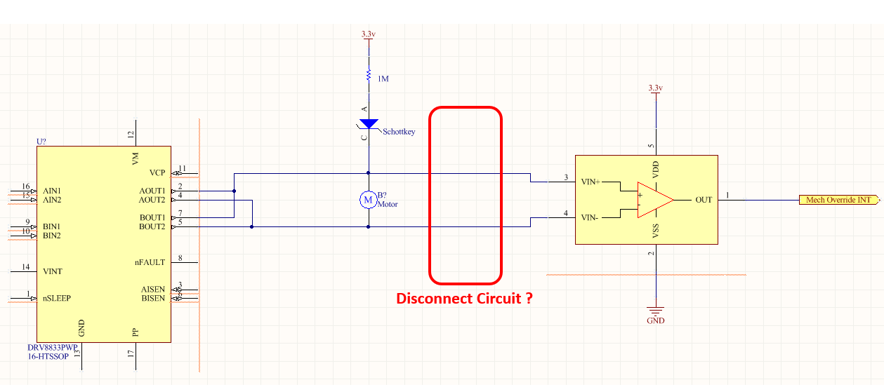
Is there a motor driver with the feature to detect if motor is connected or not ?

For example a driver connected to a DC motor

In idle state (no motor operation), the motor can be disconnected machanically from the driver.. so i need to detect it

Thanks

  • Hi Eduard,

    What are the other requirements for the motor driver (voltage and current)?

    There are external circuits that can be used to detect whether a motor is connected. One method can be found here: www.ti.com/.../slva858

    If using current regulation during startup, there will be a time where the nSTALL signal shown in Figure 4 will toggle. This is an indication of current flowing through the motor. Once the back EMF increases and the current is reduced the nSTALL signal will no longer toggle. If you do not see the signal toggle at startup, this would be an indication that the motor is not connected.
  • Hi Rick thanks for the response
    This is a DC motor that runs from 6v-8v battery with avarage current of 1A (can reach to 4A for very short time at stall)
    Your solution is good for startup.. but i need a solution for system idle state - i need to know immidiatelly (interrupt) when motor is mechanicaly disconnected from the driver

    Thanks
  • Hi Eduard,

    The DRV8848 in parallel mode would be a good choice of driver. The minimum voltage is 4V and the device can drive 4A in parallel mode.

    A slight modification to the circuit may work for you. Disconnect R1 and re-connect it from the output to VBATT. You may need to adjust the resistor values to achieve the desired voltage at nSTALL. If the motor is connected, nSTALL will be a logic high when the outputs are disabled. If the motor is not connected, nSTALL will be a logic low.
  • Hi Rick

    Sorry but i don't really understand, can you please explain in more details ? maybe simple drawing if possible
    nSTALL & R1 - do you mean to nFAULT & the 10k PU resistor mentioned in datasheet ?
    Connect it as a PU on the output ?

    Thanks
  • Hi Eduard,

    As I understand it, you want a monitor that alerts you when the motor is disconnected and the motor driver is idle. 

    By idle state, I am assuming you mean the motor driver is asleep. Is that correct?

    There are two methods shown below. One is interrupt 

    You can adjust the resistor values as necessary to minimize power. If you are extremely power sensitive, there could be other methods to turn the load on and off.

    Please note this is a concept; it has not been debugged.

    OpenLoadDetection.pdf

  • Many thanks Rick
    I'll test the 2 concepts you propose !
    Best regards
  • What are the states of the output pins when the driver is in sleep mode ?

    Is it something can be controlled ?

    How it will affect the motor check ?

  • Hi Eduard,

    What are the states of the output pins when the driver is in sleep mode ?

    >> the outputs are in high Z, but there may be a path to limit the gate to source voltage of the high side FET. We can check on this next week.

    Is it something can be controlled ?

    >> This circuit cannot be controlled.

    How it will affect the motor check ?

    >> If using method 1, there could be some additional voltage loss. If using method 2, there should be no effect.

  • Hi

    Tested method 2 - something isn't working for me, still investigating to find out what exactly i did wrong or didn't took into account

    When motor is connected - i can see logic low at "MECH Override INT"

    BUT - When motor is disconnected - there is a current path into the DRV output so i can see Approx 1.5v on the "MECH Override INT" and not the 3V...

    What is the exact state of the outputs ? What do you define as Hi-Z ? pulled to GND/VM ?

  • Hi Eduard,

    We will have to go to the lab to check this. What is the voltage on the VM, AINx, BINx, and nSLEEP pins when you are making this measurement?
  • Hi Rick

    Idle state = system is at sleep mode

    VM = 6v-8v

    AINx = BINx = logic high 3v

    nSLEEP = logic low 0v

    Thanks & Regards

  • Hi Eduard,

    There does appear to be an internal that consumes current. I will have to discuss this with the design team to find where the current is flowing. This make take a few days.
  • Ok Rick

    Waiting for your replay

    Thanks

  • Hi Eduard,

    As you found, there is a path that consumes current in method 2. Using the 100k resistor limits the current to ~15uA. If you want to raise the voltage at "MECH Override INT" node, you can decrease the resistor to 10k. The down side of this is the current draw will increase to approximately 80uA.

    From the circuit provided are you polling the "MECH Override INT" node at a low frequency? If you are, please consider modifying the circuit to insert a second NMOS transistor between the "MECH Override INT" node and the schottky diode. The drain would be connected to "MECH Override INT", the gate connected to "MECH Over Sense ON", and the source connected to anode of the schottky.

    By doing this, you can reduce the average current by the operating duty cycle. For example if you measure the current for 1ms every second and the current is 80uA, the average current would be reduced to approximately 80nA assuming there is very little leakage in this configuration. TI femtoFETs ( www.ti.com/.../femtofet.html ) are ideal for these applications due to the size.
  • Hi Rick

    I tried in the lab the next solution, seems like it works good

    My question is - should i disconnect the comparator from the motor before motor's operation ?

    Is there any concern that the comparator will affect motor's operation and/or DRV sensing (current, fault etc')

    There is different tolerances for comparator's input impedance, for the DRV also..

    So what do you think ?

    If so, how do you suggest to disconnect it ?

    Thanks

    Eduard

  • Hi Eduard,

    The comparator should not affect the operation of the DRV8833, but the DRV8833 may affect operation of the comparator.

    What is the input voltage rating of the comparator when VDD=3.3V. Are there some paths that could raise the VDD voltage?

    If there are, you should protect the comparator. This can be done by either:
    A CSD13381F4 can be placed between the motor and each input of the comparator to connect/disconnect OR
    After confirming with the comparator manufacturer, possibly adding resistors from the motor to the comparator to limit the current.
  • Thanks Rick

    I will do some tests and get back to you

    Best Regards

    Eduard