This thread has been locked.

If you have a related question, please click the "Ask a related question" button in the top right corner. The newly created question will be automatically linked to this question.

DRV10983-Q1: EEPROM programming fails

Part Number: DRV10983-Q1
Other Parts Discussed in Thread: DRV10983Q1EVM

I have a similar problem. All data is fine, but writing does not change the registers.
In the branch that I ran, the decision was not publicly published.

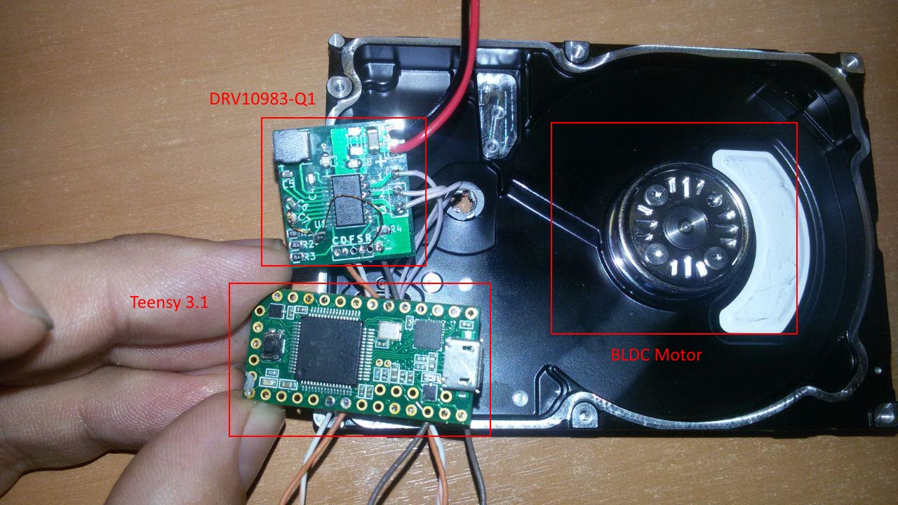
I do not have the equipment for testing and testing. I'm working with a self-made PCB:

I get access to the parameters using Arduino.
Code:

#include <Arduino.h>
#include <Wire.h>

#define I2C_DRV10983_Q1_ADR 0x52

#define Fault_Reg 0x00 //
#define MotorSpeed_Reg 0x01 //
#define DeviceIDRevisionID_Reg 0x08
#define EEPROM_Access_Code_Reg 0x31
#define EEPROM_EeReady_Reg 0x32
#define EEPROM_Iindividual_Access_Adr_Reg 0x33
#define EEPROM_Individual_Access_Write_Data_Reg 0x34
#define EEPROM_Access_Reg 0x35
#define EECTRL_Reg 0x60

void setup() {
    Serial.begin(9600);
    Wire.begin(); 
}

byte readByAdress(byte reg_adr,  unsigned int &result) { //I2C write 2-byte register
    byte i = 0, err = 0;
    byte bytes[2] = {0, 0}; 
    Wire.beginTransmission(I2C_DRV10983_Q1_ADR); 
    Wire.write(reg_adr); 
    err = Wire.endTransmission();
    if(err!=0)
        return err;
    Wire.requestFrom(I2C_DRV10983_Q1_ADR, 2);
    while(Wire.available()) 
    { 
        bytes[i] = Wire.read();
        i++;
    }
    result = ((bytes[0] << 8) | bytes[1]);
    return 0;
}
byte writeByAdress(byte reg_adr,  unsigned int value) { //I2C read 2-byte register
    byte bytes[2]; 
    bytes[1] = value >> 0;
    bytes[0] = value >> 8;
    Wire.beginTransmission(I2C_DRV10983_Q1_ADR); 
    Wire.write(reg_adr); 
    Wire.write(bytes,2);
    return Wire.endTransmission();
}
boolean flag = true;

void loop() {
    if(flag){
        int count = 0;
        unsigned int value = 0;
        unsigned int onReady = 0;
        delay(3000);
        writeByAdress(EECTRL_Reg, 0x8000); //Stop motor
        writeByAdress(EEPROM_Access_Code_Reg, 0x0000); //Reset EEPROM_Access_Code_Reg
        writeByAdress(EEPROM_Access_Code_Reg, 0xC0DE); //Set EEPROM_Access_Code_Reg
        while(onReady == 0 && count < 1000){ // Wait EEPROM ready
            readByAdress(EEPROM_EeReady_Reg, onReady);
            count++;
        }
        Serial.println("EEPROM_Access. Cycles of expectation: " + String(count));
        count = 0;
        onReady = 0;

        //Write values on shadow registers
        writeByAdress(0x90, 0x105A);   //new
        writeByAdress(0x91, 0x2F2A);   //new 
        writeByAdress(0x92, 0x0050);
        writeByAdress(0x93, 0x1B8A);
        writeByAdress(0x94, 0x3FAF);
        writeByAdress(0x95, 0x3C43);
        writeByAdress(0x96, 0x016A);
        writeByAdress(EEPROM_Access_Reg, 0x0006); //EEPROM mass access enabled && update from 0x90-0x96
        while(onReady == 0 && count < 1000){ // ожидание готовности EEPROM
            readByAdress(EEPROM_EeReady_Reg, onReady);
            count++;
        }
        Serial.println("EEPROM_Update. Cycles of expectation: " + String(count));
        onReady = 0;
        count = 0;

        //Reading shadow register values for verification
        writeByAdress(EEPROM_Access_Reg, 0x0002); //EEPROM mass access enabled 
        while(onReady == 0 && count < 1000){ // ожидание готовности EEPROM
            readByAdress(EEPROM_EeReady_Reg, onReady);
            count++;
        }
        Serial.println("EEPROM_Read. Cycles of expectation: " + String(count));
        count = 0;
        onReady = 0;
        readByAdress(0x90, value);
        Serial.println("0x90: " + String(value, HEX));
        readByAdress(0x91, value);
        Serial.println("0x91: " + String(value, HEX));
        readByAdress(0x92, value);
        Serial.println("0x92: " + String(value, HEX));
        readByAdress(0x93, value);
        Serial.println("0x93: " + String(value, HEX));
        readByAdress(0x94, value);
        Serial.println("0x94: " + String(value, HEX));
        readByAdress(0x95, value);
        Serial.println("0x95: " + String(value, HEX));
        readByAdress(0x96, value);
        Serial.println("0x96: " + String(value, HEX));

        writeByAdress(EECTRL_Reg, 0x0000); //Run motor
        
        flag = false;
        
    }
    
}


Result:

EEPROM_Access. Cycles of expectation: 1
EEPROM_Update. Cycles of expectation: 180
EEPROM_Read. Cycles of expectation: 1
0x90: 1048
0x91: 2f3b
0x92: 50
0x93: 1b8a
0x94: 3faf
0x95: 3c43
0x96: 16a

As can be seen from the results, the registers retain the default values and new data are not applied.

  • Hey Alexey,

    Please implement a 50ms delay after the EEPROM status goes high and let me know if it solves your problem. If it solves your issue, this is a known issue and plan to implement it as a requirement in the datasheet.

    If it does not, please use an oscilloscope and probe the voltage on the clock and data lines and check for noise. We've seen problems with suboptimal layout relating to the GND plane affecting I2C communcation from MCU to DRV10x before. If the clock and data seem very noisy, the GND lead can be attached at V- and the probe tip can be used at the GND pin of the device. If there is a significant voltage difference, then the GND layout could be the problem.

    Best,

    -Cole

  • Thanks for your advice, but I was not helped by the setup delay after setting EEPROM_EeReady high.

    I continue to understand further.
    Besides, how does individual access work? The algorithm is not described, although I understand that it is necessary to write the register address in 0x33 eeIndAddress, but this value is indicated only for reading in datashit. Error?

    I can not say that there are problems in the tire. The level of pullup voltage is 3.3v (alas, I can not change the noise).
    My observations:
      - writeByAdress (EECTRL_Reg, 0x8000); The motor stops, as required. But trying to read values ​​always returns 0.
    - writeByAdress (EEPROM_Access_Code_Reg, 0xC0DE); - recorded and re-read without problems.

    Next on my observations is very stable and stable behavior - when I write the values ​​in the shadow registers, their values ​​do not change, although if you set the ShadowRegEn bit (0x35 -> 0x1000) - these registers pass successfully, but subsequent attempts to write to the EEPROM or to to which they do not.


  • If someone will work with this driver as I am - without a debug board and without an I2C adapter, I think the settings calculator I wrote will help you with the settings:
      http://drv10983-q1.h1n.ru/

  • Tell me, is it possible to see the layout of the circuits in the debug board for this controller?
  • Hey Alexey,

    Unfortunately, it seemed as if this question was closed so I did not notice your response. Can you please post a separate thread with your followup question? You can click the "Ask Related Question" link on the top of this page.

    If you intend to ask about layout, can you be more specific? If you are asking if we can review your layout and schematic, then yes, we can do a review. Just post the pictures in high resolution. If you are asking about something else, please provide as much details as possible so we can help you in a separate thread.

    Thanks,
    -Cole
  • The thing is, I wanted to see the drv10983q1evm board layout for an example.
    As far as I know, such information should be posted here: www.ti.com/.../drv10983q1evm
    But the links did not work (and now they don’t work either), so I asked that question.

    But I want to tell you that I still managed to find these files and find the problem in my board.
    Thanks for your reply!
  • Hey Alexey,

    Glad to hear you fixed the problem and found the files. For anyone who is viewing this post after it is closed, the direct link to the DRV10983-Q1EVM gerber, altium, and manufacturing files can be found here: www.ti.com/.../slor125

    Best,
    -Cole