Dear TI team,
See below my customer issue with our motor driver EVM:
__________________________________________________________________________________________
I noticed a problem with the DC motor driver DRV8873H-Q1. Below is the context and the observations done.
Context:
- EVM board DRV8873H-Q1EVM (hardware version, board modified to set all slew rates availables with an external resistor, and resistors R30/R32 removed to control the driver with an external PWM done by a function generator)
- 18V power supply
- DC motor: R=3.9ohms, L=5mH (blocked for the demonstration)
- F_PWM=40kHz
- Mode PH/EN (set on GUI software): PH=0, EN=0/1
- Slew rate set to 13V/µs
- Motor connected between OUT1 and OUT2
- Wake: ENABLE
- Output states: ENABLE
- Open load detection: ENABLE
- Itrip control: ENABLE (Itrip=6.5A, Toff=20µs)
Observations:
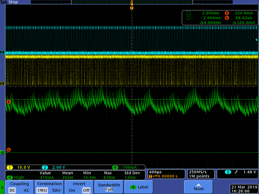
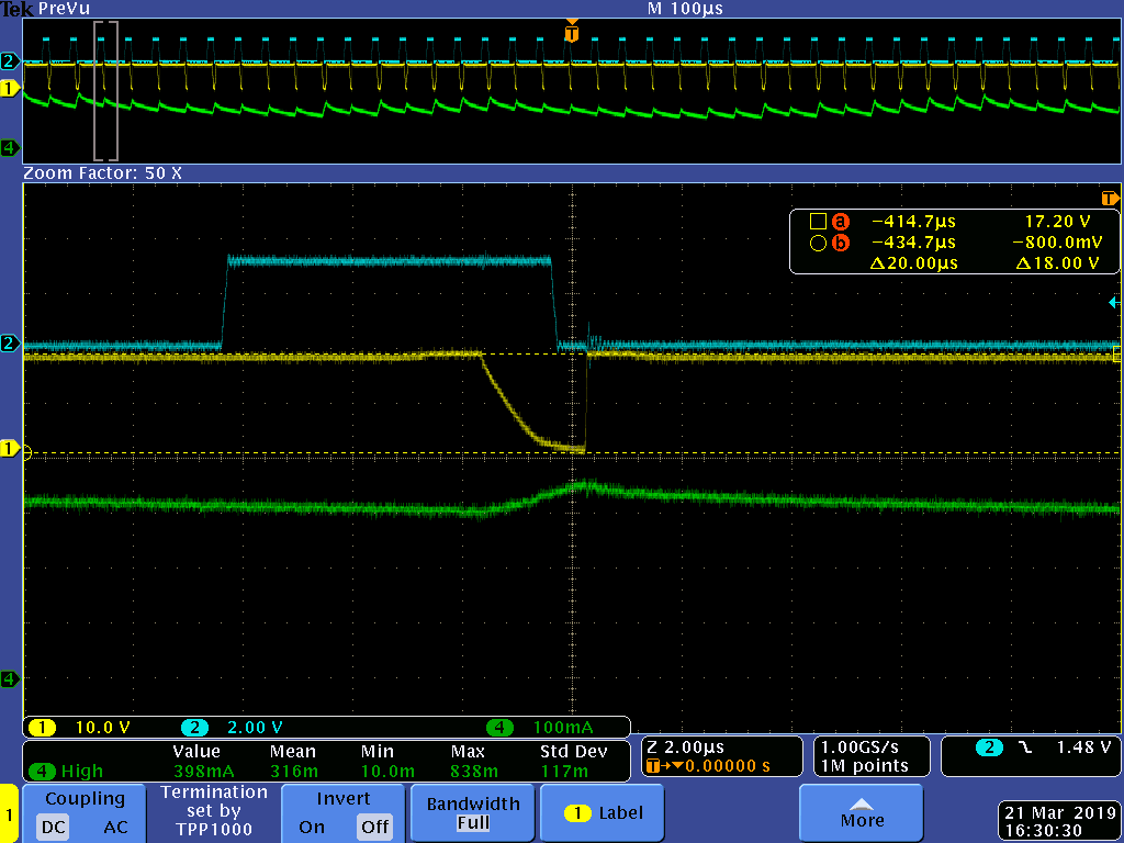
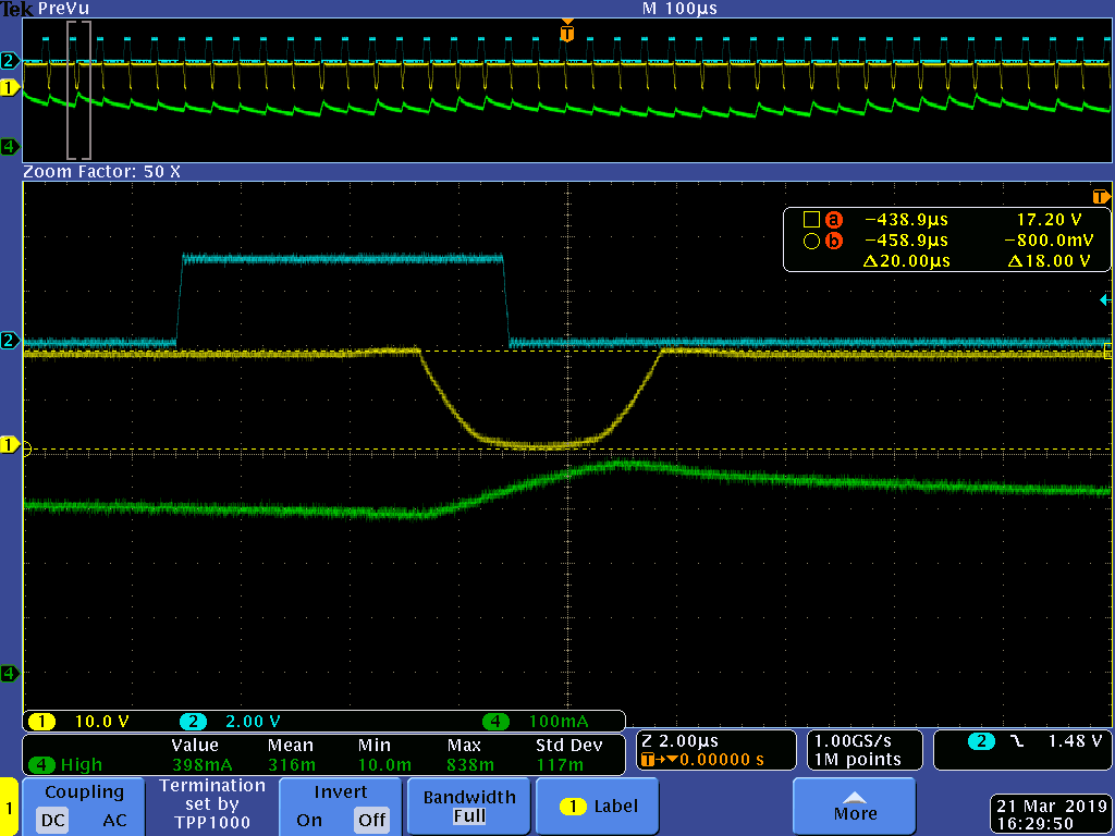
Duty cycle = 22%:
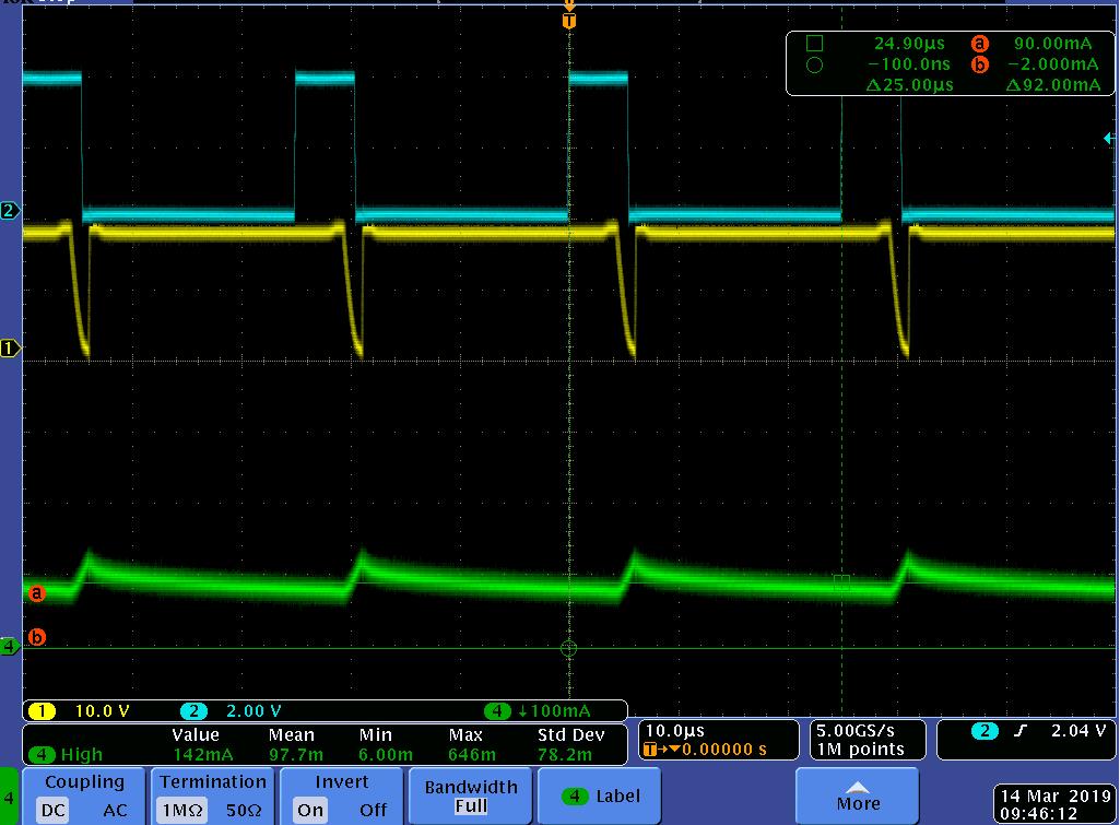
By applying external PWM (blue curve) the motor current (green) increases. The OUT1 (yellow) falling slew rate is around 13V/µs whereas the rising slew rate is much higher.
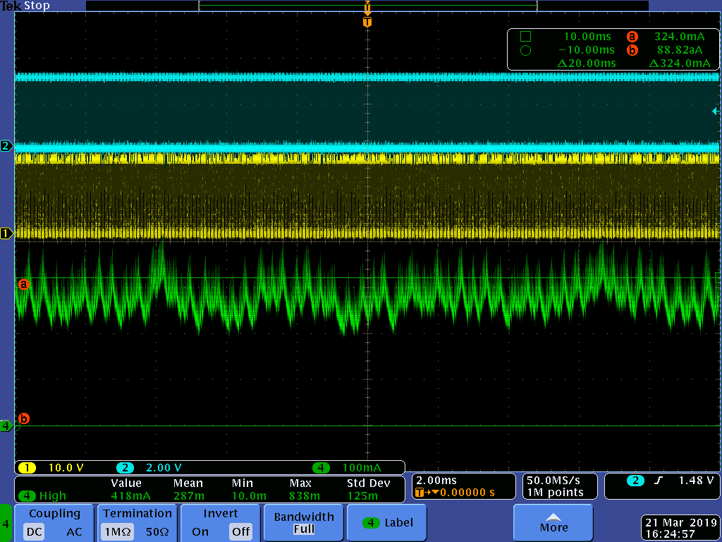
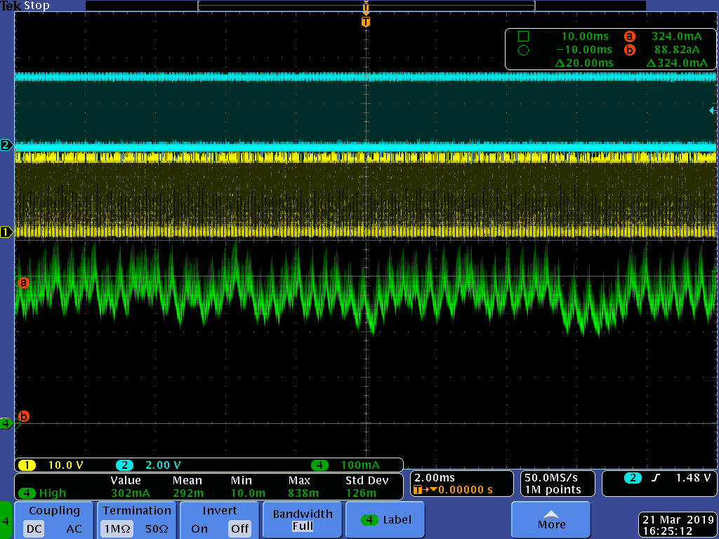
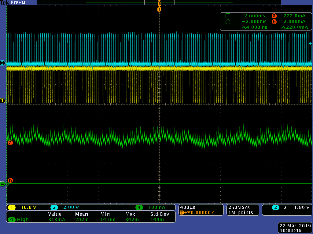
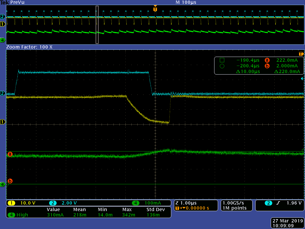
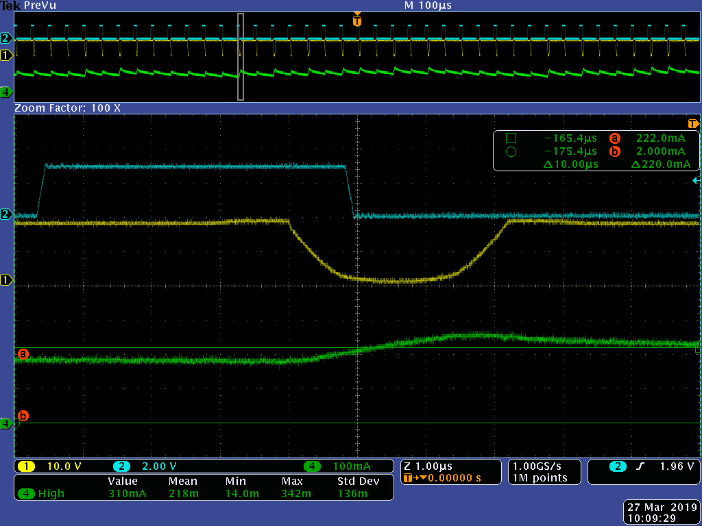
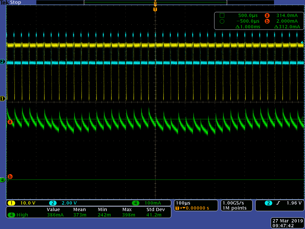
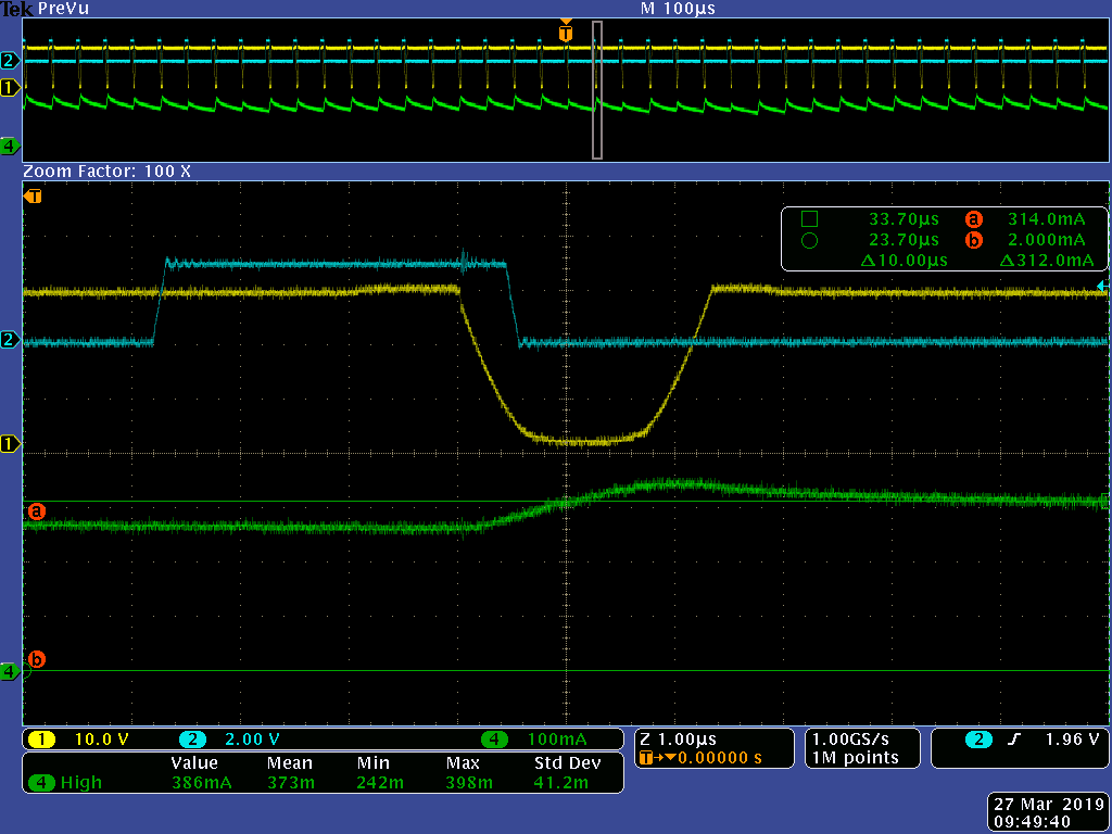
Duty cycle = 24%:

When the OUT1 seems reach 0V, the driver becomes unstable. The rising slew becomes unstable, the motor current starts to oscillates and the motor starts to vibrate. A video linked was done to show this phenomenon.
Beyond this specific duty cycle, the driver and motor behave well.
This phenomenon was observed first by driving the motor with the GUI software and was reproduced with external PWM control.
This phenomenon is also present in PWM mode by alternating the outputs between H/L and H/H states (does not append in PWM mode by alternating the outputs between H/L and Hi-Z/Hi-Z states).
This phenomenon is much more present with low slew rates configurations and vibrations of the motor are stronger.
This phenomenon was reproduced with a power resistor instead of a motor on the outputs.
Did you already noticed this behavior or could it be a default of my EVM?
Where does it come from?
Does it happen with the DRV8873S driver too?
Thanks you for your interest
_________________________________________________________________________________________