This thread has been locked.

If you have a related question, please click the "Ask a related question" button in the top right corner. The newly created question will be automatically linked to this question.

DRV8837: Bulk capacitance and max current drawn

Part Number: DRV8837
Other Parts Discussed in Thread: CSD25310Q2

Hello,

I want to ask about the max current that is drawn from my system using DRV8837. From the related question that previously has been verified I think a new topic is more suitable so the discussion can be focus.

From my previous related question, I tested my system at stall and the drop voltage on the driver (Rds) is quite high.

As a summary, I use a motor with rated voltage of 3.5 V and the stall current at 3.87 A.

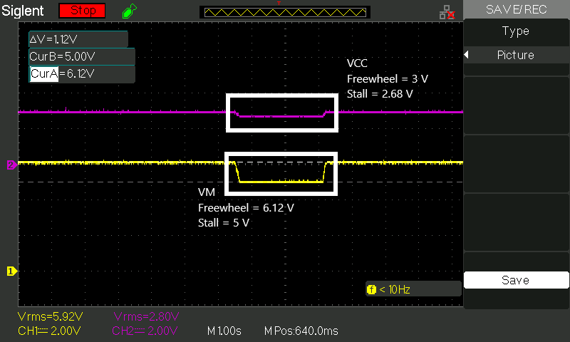
  • If I drive the driver with 6.0 V then stall the motor, the stall current provided by driver is about 1.7 A
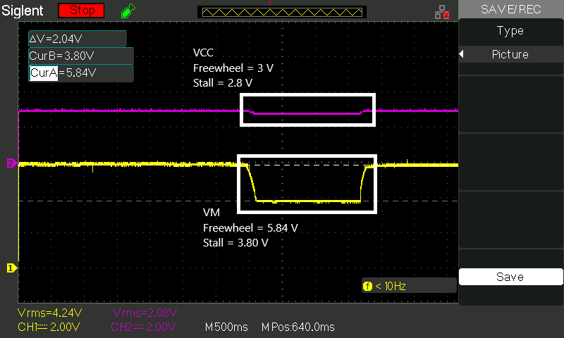
  • If I drive the driver with 3.5 V then stall the motor, the stall current provided by driver is about 1.2 A

I'm confused with this not so ideal result. The datasheet for DRV8837 states that the amount of local capacitance needed depends on a variety of factors such as the highest current required by the motor system.

So my question is:

  1. Based on the experiment, even at 3.5V I can't maximize the DRV8837 to at least close to its max current 1.8 A. I thought that should not be so low, probably around 1.5A.
    Does this has anything to do with the bulk capacitance? In other words, does the local bulk capacitance can determine the max continuous current that can be delivered by the driver?

As a note, I check the schematic and the driver block only has 0.1uF capacitor on its VM pin. There is a 10uF capacitor however that is on the input of the system that feeds to buck converter input. The input (+) side is parallel to VM on DRV8837 and VIN on buck converter (intended for battery positive terminal).

Kind regards,
Pranata

  • Hi Pranata,

    Would you please provide scope capture of either the current or the voltages at the outputs?

    This will help determine how the DRV8837 is reacting to the stalled motor.

    Also, please provide a scope capture of the VM and VCC voltages when the motor is stalled. If VCC is dropping below the Vuvlo threshold, the DRV8837 may be disabling the outputs. A local bulk capacitor on VCC can help prevent voltage drops on VCC.

  • Hi Rick,

    Thank you for your suggestions, pardon me if this post might be long. Please forget the 3.5V motor that I posted on the first post.

    I have tested again using a better motor with clear spec from the supplier. Here are the specs for the motor:

    • Rated voltage 6 V
    • Rated load 10 mNm
    • No load speed 5927 rpm
    • No load current 0.075 A
    • Rated load speed 3669 rpm
    • Rated load current 1.142 A
    • Stall current 2.88 A
    • Stall torque 26.2 mNm
    • It means the motor resistance (6 V / 2.88 A) = 2.08 ohm

    I tested using power supply and batteries as the source for my board, so I will separate the results on two posts.

    The software just control the input to 100% full PWM.

    I probe the supply voltage, motor voltage (both terminal or output of DRV8837), VM and VCC.

  • Results using Power Supply set to 6 V, stall current around 1.6 ~ 1.8 A

    • Supply voltage and motor voltage drop

    • VM and VCC drop

  • Results using 4xAA Batteries with Voltage 6 V, stall current around 1.3 A

    • Battery voltage and motor voltage drop


    • VM and VCC drop
  • I am still confused about the analysis here.

    1. When testing with power supply, the motor voltage drop to 4.4 V and VM is 5 V.
      So theoretically the stall current could be (4.4V / 2.08 Ohm) = 2.11 A.
      My result is around 1.6 ~ 1.8 A, this means the driver has been push to the max.
      The difference between VM and  motor voltage is (5 V - 4.4 V) = 0.6 V.
      With stall current around 1.7 A, the Rds = (0.6 V / 1.7 A) = 0.353 Ohm.

      Is it correct to analyze the Rds like this at stall?


    2. When testing with battery, the motor voltage drop to 3.36 V and VM is 3.8 V.
      The difference between VM and motor voltage is 0.56 V.
      With stall current around 1.3 A, the Rds = (0.56 V / 1.3 A) = 0.430 Ohm.

      Theoretically the stall current could be (3.36 V / 2.08 Ohm) = 1.6 A.
      However my stall results just around 1.3 A.

      Do you have any idea why the stall current is low when using the battery?


    Thank you Rick

  • Hi Pranata,

    Sorry, I am not quite sure what the images are showing. Please allow me to explain what I believe should be measured.

    M1 - VM or VBATT voltage at the input of the DRV8837 when stalled

    M2 - The higher of OUT1 or OUT2 when stalled

    M3 - The lower of OUT1 or OUT2 when stalled

    I -     Current through the motor

    With these measurements, you should be able to determine the RDSon of the outputs and determine the maximum current through the motor when stalled.

    NOTE: The current will vary based on the VM voltage at the pin of the device. As the voltage lowers, the RDSon will increase.

    The formula for measuring the RDSon of the high side FET is

    RDSonHS = (M1 - M2) / I

    The formula for measuring the RDSon of the low side FET is

    RDSonLS = (M3) / I

    The max current through the motor then becomes:

    Imax = M1 / (Rmotor + RDSonHS + RDSonLS)

    Please let us know if this explains what you are seeing.

  • Hi Rick,

    I have updated the pictures on previous post, hopefully it will make it more clear. I tested my board using power supply and battery. For each test there are two pictures, first I probe the voltage on the supply side and the motor (both terminal), and second I probe the voltage on the VM and VCC on the driver. So this test lack the M2 and M3 that you mention because I do not probe the OUT1 or OUT2 against the ground.

    I have tried to probe the M2 and M3 and calculate the current based on your formula. It is close with the max current that I recorded at stall. For example when using the battery, your suggested calculation gives me max current Imax around 1.4 A while my measurement get around 1.3 A. Also when using power supply, the calculations Imax around 1.8 A while my measurement get around 1.7 A.

    From both tests (confirmed from the probe pictures and today's test), I see that there is quite a difference between V supply or battery and VM at stall. It is always V supply > VM at stall. From my result it can be 0.4 ~ 0.6 V difference.

    1. As you suggested, M1 is VM or VBATT voltage so I think these two values should be as close as possible.
      Do you think this is an anomaly?

    2. If this is an anomaly, do you think it is because the lack of bulk capacitor? Any idea how to make it as close as possible so the system can deliver more current?

    Kind regards,
    Pranata

  • Hi Pranata,

    From both tests (confirmed from the probe pictures and today's test), I see that there is quite a difference between V supply or battery and VM at stall. It is always V supply > VM at stall. From my result it can be 0.4 ~ 0.6 V difference.

    1. As you suggested, M1 is VM or VBATT voltage so I think these two values should be as close as possible.
      Do you think this is an anomaly?

    No, this is not an anomaly. Typically the batteries will have more series resistance. Based on the current through the motor (3.36V when stalled / 2.08 Ohms = 1.61A), the series resistance from the battery is (5.88V - 4.08V ) / 1.61A = 1.11 Ohms.

    You can do a web search for series resistance alkaline battery and find plenty of material. Remember that you have 4 batteries in series so each battery has ~270mOhms of resistance.

    1. If this is an anomaly, do you think it is because the lack of bulk capacitor? Any idea how to make it as close as possible so the system can deliver more current?

    A bulk capacitor helps when PWM'ing, and at initial turn on and turn off. Once the system is operating at 100% duty cycle, the bulk capacitor has little effect.

    Finally, please note you should not expect more than 1.9A from the DRV8837. If the current exceeds 1.9A, the outputs may disable for approximately 1ms due to overcurrent protection.

  • Hi Rick,

    Thank you for your help and assistance! You have helped us to analyze this using your suggested calculation.

    I have thoroughly checked my PCB and schematic, it seems some of the design is not so correct. The PCB uses TI CSD25310Q2 as battery protection, so there is a trace from the 6V output of CSD25310Q2 to driver VM. The trace is only 8.6 mil and based from IPC recommended, it is not suitable for current as high as ~ 1.8 A.

    When I probe the 6V output of CSD25310Q2 and the driver VM, there is a difference around 0.2 V when stall. So even if it is just a trace, the resistance seems quite high.

    I think I need to debug the PCB board first. If you have any more advice, it is much appreciated.

    I will verify this thread as resolved.

    Thank you Rick,
    Pranata