This thread has been locked.

If you have a related question, please click the "Ask a related question" button in the top right corner. The newly created question will be automatically linked to this question.

DRV8848: Question for DRV8848 to drive a unipolar motor

Part Number: DRV8848

Hi Experts,

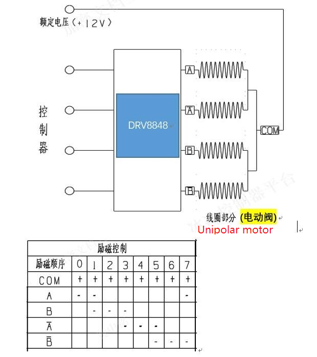
Our customer wants to use DRV8848 to drive a unipolar motor like below block diagram showing, can you help to check if we can use it?

From the datasheet description, we do not find any info regarding to such application, not sure if it will workable or not.

Thanks.

  • Hi Experts,

    Add some test waveform as attached on customer side for this application, and it looks like it does not match our datasheet bridge control true table. Can you help to check what's problem in here?

    DRV8848 Issues_Hisense_2-10-2020.pdf

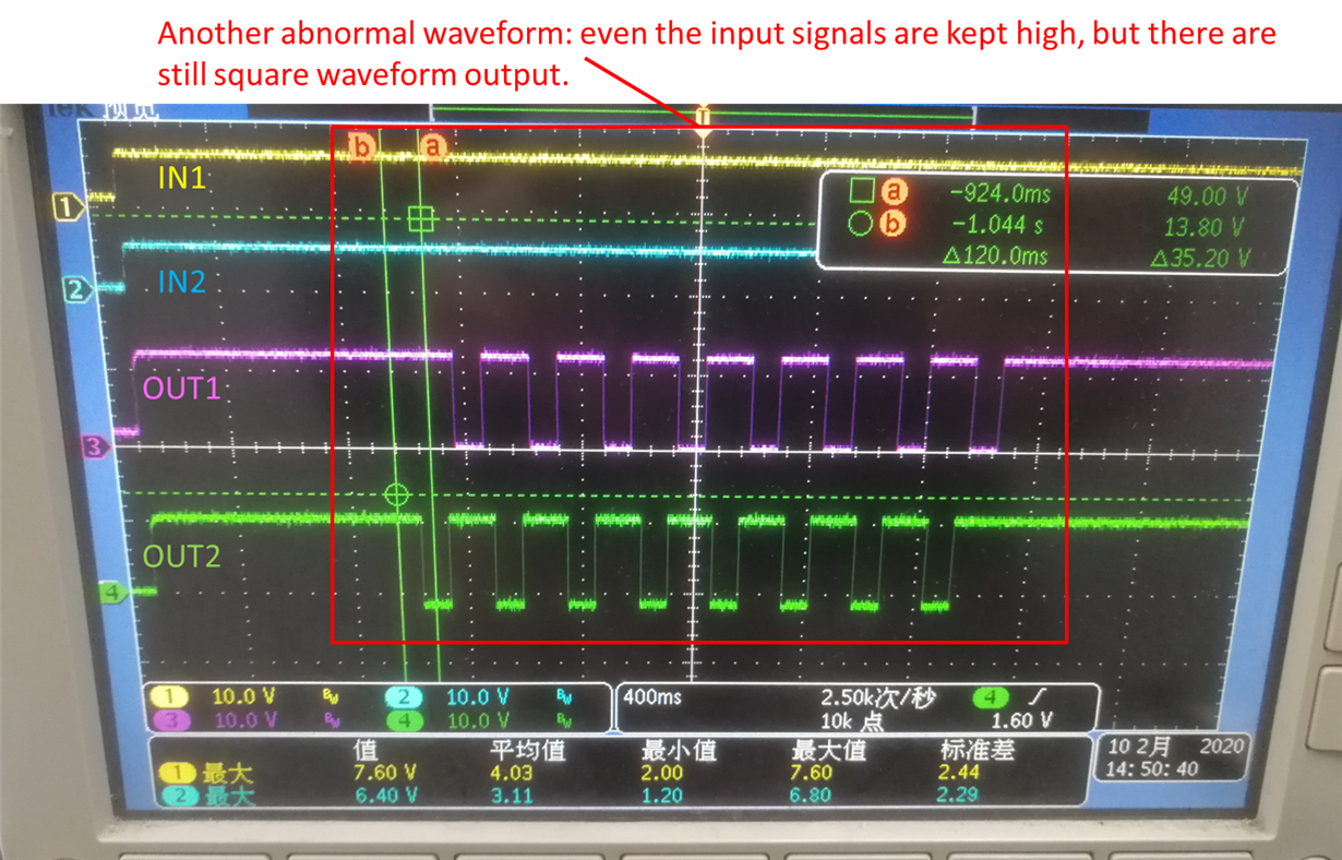
  • Add another abnormal waveform customer captured:

  • Jacky,

    The DRV8848 bridge control table assumes the winding across OUT1 and OUT2 without center tap connection. After modifying the connection, we could get different output voltage and get more complicate when the current regulation loop or OCP is triggered.

    Can you remove the center tap connections?

  • Hi Wang,

    As this is used for the specific unipolar stepper motor with the center tap which can not be removed, so customer can not remove it.

    Based on my today's experiments on our EVM, we find that it could be related to AINx ports. Currently we checked the BINx ports which worked fine with expected output logic(BINx=L, BOUTx=L; BINx=H, BOUTx=H;). Some strange behaviors are related to AINx ports, please find my test results as below:

    1. Test conditions:
      1. VM=12V, AINx and nSleep logic high is 5V, low is 0V.
      2. No any load on the AOUTx ports.
      3. VINT shorts to VREF directly.
    2.  Test procedure 1:
    1. Put AIN1/2 pins to low, 0V.
    2. Put nSleep pin to low, 0V.
    3. Apply 12V power supply to device, and then put nSleep pin to high, 5V.
    4. Disconnect the two AIN1/2 pins to float.
    5. Just apply low or high logic to only one AINx pins, AIN1 or AIN2, you will not see any output change on the corresponding AOUTx pins. --- Is the expected behavior?
    • Test procedure 2:
      1. Put AIN1/2 pins to low, 0V.
      2. Put nSleep pin to low, 0V.
      3. Apply 12V power supply to device, and then put nSleep pin to high, 5V
      4. Only disconnect one pin for AINx to float, and keep another pin to fixed logic, low or high.
      5. Just apply low or high logic to the float AINx pin, you will see the correct AOUTx logic along with the AINx logic.

    Can you help to explain the above behavior on our EVM?

    Thanks a lot!

  • Jacky,

    When AIN1 or AIN2 are set to Hi-Z and not in parallel mode, the output driver maintains the previous state (See datasheet page 10 under table 1). BIN1 or BIN2 has 200k internal pull-down resistor (check the spec table). Floating BINx means BINx low to the internal circuit. That can explain your test procedure 1 and 2.

    BTW, the center tap which can not be removed. But, when you connect it to EVM, you can leave it floating. When you leave it floating, what do you have? I want to verify the correct DRV8848 logic first. At the same time, we can observe the motor behave. That may be a potential solution.

  • Hi Wang,

    The previous abnormal output logic for DRV8848 should be cased by unsuitable control for AINx pins on customer's board. As we further checked customer's schematic they used two open drain GPIO with relative high pull up resistors to drive the AINx pins, so it could trigger this special AINx pins function. Customer has tried to change to other general GPIO pins which gets the correct logic now. They will do more tests further and feedback to you if we have.

    Thanks for the support. 

  • Jacky,

    Great! Please let me know if you have any update. We don't have many unipolar motor applications. This may be a good one.