This thread has been locked.

If you have a related question, please click the "Ask a related question" button in the top right corner. The newly created question will be automatically linked to this question.

DRV8821: The Bridge A/B control problem.

Part Number: DRV8821
Other Parts Discussed in Thread: DRV8823

Hello sir:

About DRV8821 control, we meet a problem need help.

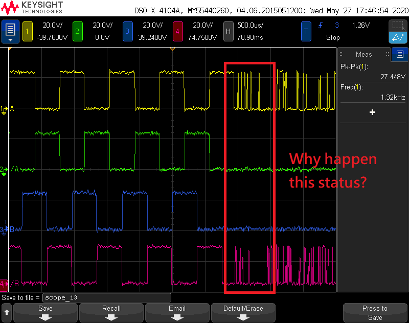
The below picture is catch from Scope and you can find the B Bridge is slow 1/4 wave of A Bridge.

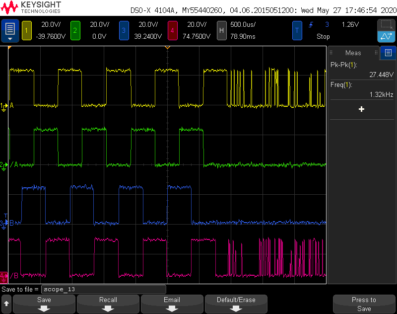
From DRV8821 datasheet, I can find the "Figure 10. Block Diagram" has a "APHASE/BPHASE" control, but I don`t know how to control it.

Please tell me how to control then A/B Bridge can start on same time.

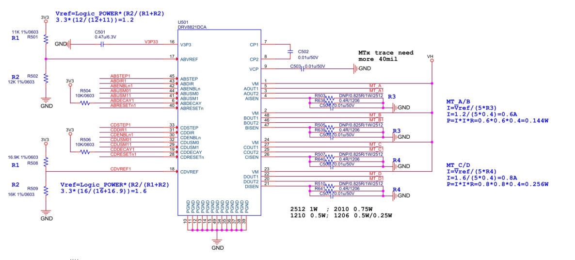
Below picture is my schematic, provide for reference.

Thank you.


  • Hi Steve,

    Figure 10 is showing internal connections from the indexer to the outputs.

    The DRV8821 uses a STEP/DIR interface. The AOUTx and BOUTx are designed to operate 90 degrees out of phase to control a stepper motor.

    If you want to control the AOUTx and BOUTx directly, please consider the DRV8823. The device has a serial interface.

  • Part Number: DRV8821

    Hi Rick:

    Very thanks for your information.

    For this issue, I want to know that why happen this status as blow picture red ring?

    If you can give me your E-Mail address, I can send the video to you for reference.

    You can hear the voice for Step Motor work normal or not.

    My E-Mail: steve.yeh@micromax.com.tw

    Thanks for help.

  • Hi Steve,

    Your threads have been merged to keep the information in one place.

    Arrangements will be made for you to send the video.

    In the scope capture, it appears the outputs A and A/ are entering current regulation once the STEP input is stopped. this is expected if the load current exceeds the Ichop limit.

    The outputs B and B/ also appear to be entering current regulation, but it is more difficult to interpret.

  • Dear Rick,

    Is it possible the control software issue or not?

  • Hi Steve,

    Based on the videos, it appears there could be a software control issue.

    The video shows one system operating correctly and one that appears to stall soon after beginning.

    This can be due to 

    1) running the motor too fast at the system voltage

    2) starting the motor too fast

    3) accelerating to target speed too fast

    4) not enough torque

    Because the motor started and then appeared to stall, number 3 above may be the cause.

    Please change the acceleration rate first (number 3).

    If that does not work, please lower the final motor speed (number 1).