

What happens when you connect a stepper motor to the driver and power up the system? Ideally, the stepper motor should begin turning, but what if the motor does not move? How do you find the problem? Is the problem with the motor, the driver, the firmware, the power supply, or somewhere else?
Listed below are some simple techniques that can help determine the cause. Access to an oscilloscope (and current probe), adjustable power supply, and multimeter will aid in debugging.
Steps to perform
Please refer to https://e2e.ti.com/blogs_/b/industrial_strength/archive/2013/09/25/debugging-101 for basic debugging suggestions for all types of motor drivers. Some of the links are obsolete, but the information in the blog is useful.
Assuming the board has been checked and powers up properly, the steps below can help find the source of the problem.
Are the inputs and outputs at the correct voltages, and the current level of the supply correct?
Disconnect the stepper motor and issue STEP commands. The AOUTx and BOUTx outputs should be toggling between VM and GND. If using microstepping, there could be small amounts of time when the voltage is neither VM nor GND. See the image below for examples.

If this is not observed, determine why the outputs are not correct. Are the inputs correct?
Once the inputs are correct and the outputs are toggling, it is time to connect the load and try again.
Is nFAULT asserted? If so, why? If the device has a nHOME pin, is it asserting at the proper time?
The nFAULT pin is a valuable debugging tool. Use the fault response table in the datasheet to determine the fault. Some devices have a nHOME indicator instead of nFAULT. nHOME can also aid when debugging. If the nHOME asserts at incorrect times, determine why.
If the inputs and outputs are correct, is one of the following problems observed?
Is the motion jerky motion at low speed? Possible causes to consider are:
- Broken wire or wire not connected
- Not enough current
- Operating in resonant area
- Add damper or use microstepping
Does the motor stall? The motor may stop spinning if one of the following conditions occur:
- initial speed too fast or speed is too fast for voltage
- accelerating/decelerating too fast
- changing microstep rate up or down on the fly
Changes in microstepping mode are similar to increasing or decreasing the speed of the motor. For example a 1.8 degree/step motor is operating at 12800 steps/second at 1/64 microstep mode. This equates to 60 RPM. Changing to full step mode changes the speed from 60 RPM to 3840 RPM instantly. The motor may not be able to change this quickly.
Are multiple drivers on the PCB? Is it specific to one location? If yes, check the schematic and layout.
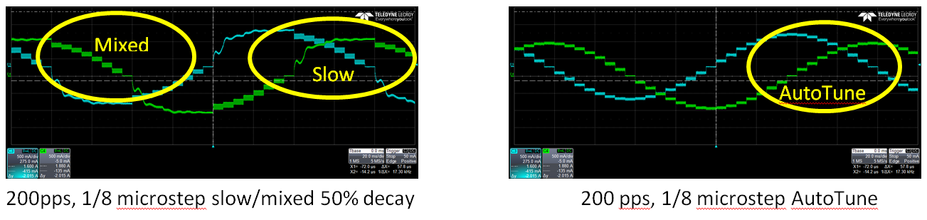
Is the current correct? Examine the current using a current probe if possible. The images below show current regulation using a DRV8846 micro-stepping with a current probe. If the current is higher than expected when using slow decay, lower the VM voltage or change the decay.
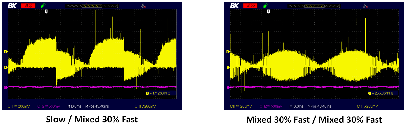
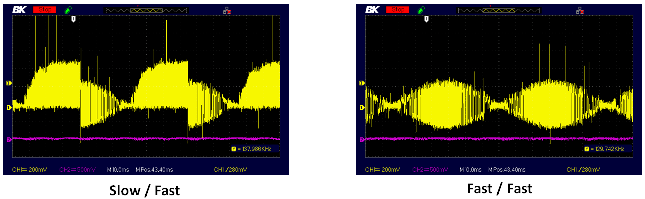
If a sense resistor is used for current regulation, the current waveforms can be seen monitoring the voltage at the sense resistor. Below are examples of current regulation at the DRV8880 sense resistor. Notice the voltage at the sense resistor using slow decay looks different when compared to other decay modes.

If problems are still observed after all of the above have been tried, please post on the forum. Please provide all the information you have collected, including:
- System Voltage
- Motor specification (R/L/V/I)
- Schematic snippet of device and connections if possible

