This thread has been locked.

If you have a related question, please click the "Ask a related question" button in the top right corner. The newly created question will be automatically linked to this question.

DRV8872: Current Decay Issue

Part Number: DRV8872
Other Parts Discussed in Thread: DRV8876

Hello,

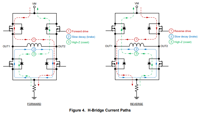
I am attempting to drive a motor using the DRV8872 driver. I am having troubles with driving at low duty cycles. I found on another thread someone was having the same issue, and they switch from the fast decay to slow decay braking, and that solved there issue because the average current was higher due to the slow current decay. So I changed to slow decay braking as well. My problem is that even using slow decay braking, the current is dropping off immediately, rather than a nice decay. 

Schematic:

(Note that R14 was decreased to 0.2 ohms allowing 1.75A before the current trip).

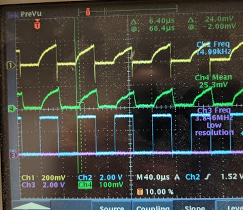
Scope image of fast Decay Mode:

Yellow: ISEN

Blue: IN1

purple: IN2

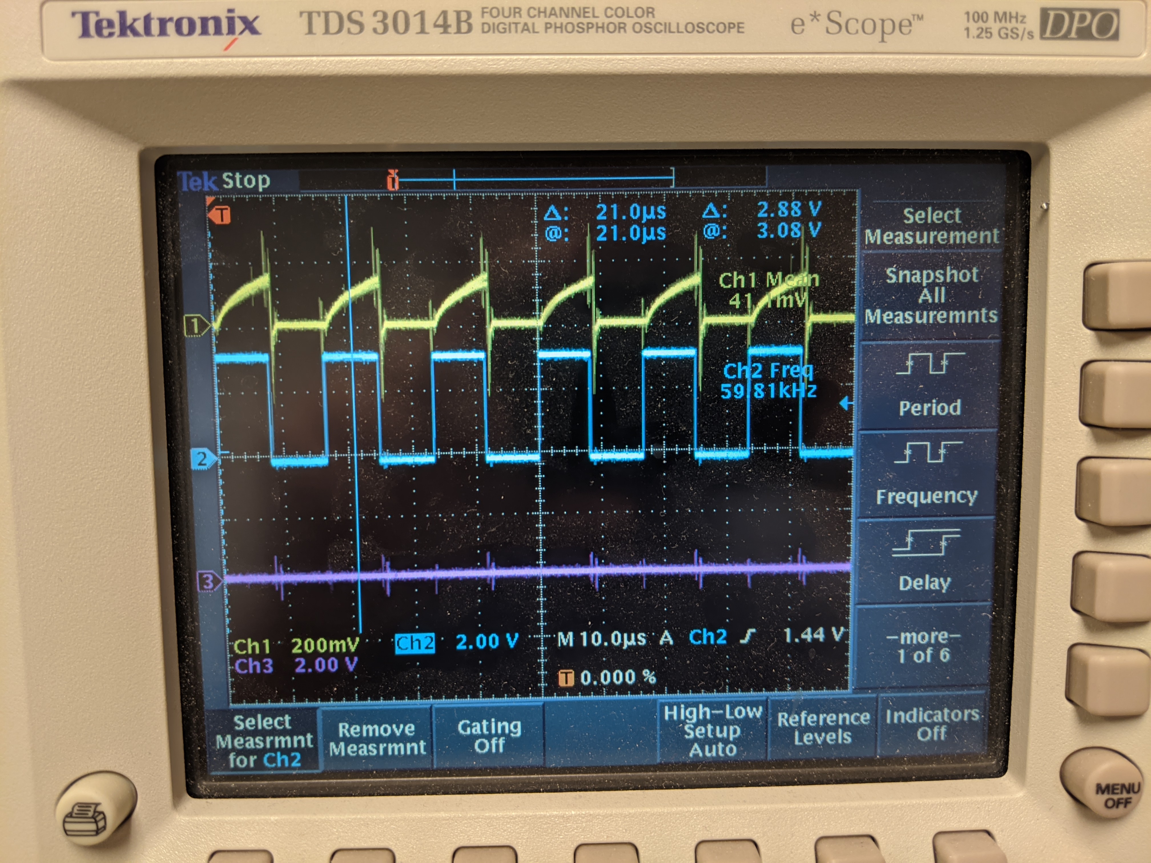
Scope image of slow Decay Mode:

Yellow: ISEN

Blue: IN1

purple: IN2

I would expect the current on the 2nd scope image to have a nice decay to it, rather than a drop right to zero. I would expect it to look like the following spice model output. 

Any help is greatly appreciated!

Thanks,

-Aaron

  • It looks like some of the pictures failed to come through. They are attached here:

    Schematic:

    Fast Decay Mode:

    Slow Decay Mode:

    P-SPICE Simulation:

  • Hi Aaron,

    Can you take another scope shot for both cases and zoom in to show one PWM cycle. It is a bit difficult to see the current decay time from the current time scale. 

     Also, can you measure the current using a current probe if you have one. Measuring the ISENSE voltage, although it does give a good estimate of the output current, is not as accurate as using a current probe.

  • Hi Pablo,

    Not a problem getting more scope images, attached below. Unfortunately we do not have a current probe at this time and the ISENSE is the best I can do.

    Fast decay:

    fast decay, very zoomed:

    Slow decay:

    Slow Decay Very Zoomed:

    I do see that in the slow decay mode it is decaying slower, but at a much smaller scale than I had expected. Why are we looking at nanoseconds instead of microseconds like the spice model suggests for a motor? I would expect the fall time to be slower than the rise time. 

    Thanks for the help,

    -Aaron

  • Hi Aaron,

    Thank you for providing the information.

    The reason why you're not seeing any voltage in Rsense during the decay time is because the current is being recirculated through the two low-side FETs. So no current is flowing through the Rsense resistor. There are devices such as the DRV8876 that use internal current mirrors to measure the current which allows for current monitoring even during the decay (or OFF) time. However, with the DRV8872, the only way to view the current during the decay period is by using a current probe.

  • Pablo,

    That does make a lot of sense. A few follow-up questions:

    1. Does that mean when I was using fast decay mode, this was an accurate current measurement, because the other low-side FET was off?

    1a. Can you help me understand why the motor does not rotate backwards in the fast decay mode?

    2. We measured the velocity of the motor slowed down while going from fast decay mode to slow decay mode. I would have expected the velocity to increase if the average current increased. Can you help me understand this? 

    Thanks,

    Aaron

  • Aaron,

    1. Fast decay mode can be interchangeable with High-Z (coast) decay mode in the case of the DRV8872. Note in coast mode, the H-bridge becomes disabled and the current flows through the body diodes of the FETs. You can read more about the different types of decay modes in this app-note.
    2. During fast decay, the motor does not reverse direction becomes the inductance of the motor prevents the current from changing direction immediately. Usually, the H-bridge goes back into driving mode before the current has enough time to change direction.
    3. I don't see how the motor speed would be affected by the decay mode. Was it a significant speed changed you noticed between the two modes? 

  • Hi Pablo,

    1. For question #1, to be clear, that image shows the current go through the Rsense in High Z mode, therefore, the current reading over Rsense should be accurate? If not, please clarify. 

    2. But we see the current decay very rapidly from the inductor. It only takes a tiny fraction of the off time to get back to 0. Why does the current not become negative after it hits zero, and cause the motor to rotate the opposite direction?

    3. The difference in speed seems to be largely effected by pwm frequency as well. At low frequencies there is a huge difference between fast decay / high z, and slow decay. Data shown below. 

    50% Duty Cycle
    Frequency Slow Decay Velocity Fast Decay Velocity %Diff
    .25KHz 0.28 2.7 -90%
    5KHz 0.61 2.57 -76%
    15KHz 1.46 2.4 -39%
    30KHz 1.44 2.17 -34%
    60KHz 1.43 1.975 -28%
    120KHz 1.39 1.56 -11%

    The velocities are in mm/sec using a lead screw and large gear reduction. 

    -Aaron

  • Hi Aaron,

    1. The current flowing through the resistor changes direction when in fast decay so the current measurement through Rsense will not be accurate. 
    2. Like I said before, using Rsense to measure current during the decay period (regardless if it is coast or fast decay mode) will not accurately show the exact current though the load. In order to accurate measure current, a current probe will be needed. 
    3. Let me research this a bit more. I will post a reply by 10/13 with an explanation.

  • Hi Pablo,

    On my end we were able to acquire a current probe and we were able to verify the slow decay vs fast decay current. I think the reason that the velocity decreases when going to the slow decay mode is because the current goes negative during the off period. Below is a scope images of the current (green) for fast decay mode and slow decay mode for a 15KHz PWM 50% Duty Cycle. 

    15 KHz, 50% Duty Cycle, Fast Decay -

    Green = current probe, 100mV = 1A so 1A per division

    Yellow = Rsense, Blue = input 1, Purple = Input2

    15 KHz, 50% Duty Cycle, Slow Decay -

    Green = current probe, 100mV = 1A so 1A per division

    Yellow = Rsense, Blue = input 1, Purple = Input2

    I believe the current is going negative due to back emf. Is there a way to mitigate the effect of the negative current?

    It seems that the negative current is the motor fighting against the direction of rotation and actively slowing down the motor.

  • Hi Aaron,

    Thank you for providing the scope images.

    Since the frequency is low, the H-bridge stays in the decay period for longer which can  be enough time for the current in the inductor of the motor to dip slightly negative. If the PWM frequency or duty cycle is increased, the TOFF period will be lower which can prevent the current from going negative for some time. The negative current should not affect the performance of the driver in any way. I suggest increasing the PWM frequency or duty cycle until the desired motor speed is achieved. You might have to choose slightly different PWM frequencies or duty cycles to achieve the same speeds when in fast or slow decay. 

    I hope this answer your questions


  • Good Morning Pablo,

    At 60KHz, 50% Duty Cycle, the current still dips negative. Do you have any suggestions schematically to reduce the effect? We are trying to balance torque and velocity. Higher frequencies are not giving the torque we need, and lower frequencies reduce the velocity due this negative dip. 

    Thanks,

    Aaron

  • Hi Aaron,

    To balance torque and speed, I suggest choosing a lower frequency that meets the torque requirements of your design and increase the duty cycle until the desired speed is reached. 

  • Pablo,

    Thank you for your continued help on these issues. I feel that I have a much better understanding of the driver and the current decay issues now. 

    Thanks,

    Aaron