This thread has been locked.

If you have a related question, please click the "Ask a related question" button in the top right corner. The newly created question will be automatically linked to this question.

UC2625: Clarification on voltage-mode speed control

Part Number: UC2625
Other Parts Discussed in Thread: UC1625-SP, DRV8343-Q1, DRV8306

Hello,

I am trying to set up the UC2625 in voltage-mode.

I looked around this forum and found this post https://e2e.ti.com/support/motor-drivers/f/38/p/612755/2382057?tisearch=e2e-sitesearch&keymatch=UC2625#2382057 

that linked to this picture (from this application note: https://www.ti.com/lit/an/slua106/slua106.pdf) as a reference for setting the chip for voltage-mode:

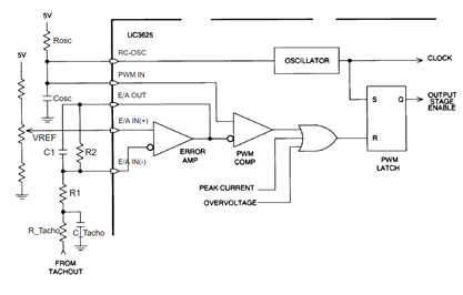
I would like some clarification on how to select values for C1, R1, and R2.

(from some digging around on google, it looks to be something like this but I'm not sure)

By the way, there appears to be an error in the description of the reference design in the UCx625 datasheet. The design claims to be operating in voltage-mode, but the speed does not change as the voltage changes. (Figure 15 in https://www.ti.com/lit/ds/symlink/uc2625.pdf?ts=1606093408447)

Thanks,

Daniel

  • Hi Daniel,

    Sorry, your image did not come through, could you please repost it?

    Best regards,
    Omar

  • Hi Omar,

    Sorry about that. 

    To clarify, the circuit appears to look like an op-amp integrator with DC gain control (as in the picture).

    However, unlike in the picture, this circuit has E/A+ set to the tachometer output instead of ground.

    Thanks,

    Daniel

  • Hi Daniel,

    Yes this is an op-amp integrator with DC gain control topology.

    EA+ should be somewhere between 1 and 2.2V to set the PWM threshold. This is because PWM_IN is tied to RC-OSC which will see a 1-2.2V sawtooth waveform and PWM_IN's level sets the pulse width of the PWM. To configure the amplifier to filter the feedback coming from the tachometer the cutoff frequency must be set below the PWM frequency. This is calculated using f(cutoff) = 1/(2*pi*C*R2). For example, with a typical 20kHz PWM it might be reasonable to start with a 5kHz cutoff.

    Based on the datasheet, the tachometer will go high for 220us every time a hall sensor input changes. For example, if you have a 3000rpm maximum speed motor, at 3000rpms you would be seeing 50 mechanical revolutions per second. You would multiply this times the number of pole pairs, in this example lets say 4, and then by the 6 hall sensor state changes per revolution (50x4x6x220=.264.) Then we can multiply this by the output voltage of tach_out pin which is 5V to get the averaged input voltage of 1.32V (without gain.) To select your gain in this case, you would divide the PWM_IN voltage at maximum duty cycle by the input voltage, i.e. 2.2V/1.32V, or a gain of approximately 1.67V/V. You can then use the gain equation Gain=R2/R1. Also, I would start with a mid-range value for R2 like 10kOhms, and derive the remaining components using the other equations. 

    You will of course have to change these calculations for your system but I hope this is a good starting point. I would also like to point out that this is a very old part (the app note is dated for 1999, but the part may be even older.) We have newer parts that require less complicated analog control. Could you share any details about your system that I could use to make recommendations for a newer, easier to use part?

    Best regards,
    Omar

  • Hi Omar,

    This is an incredibly helpful response. Thank you, this is exactly what I wanted to know.

    Yes, I would be very open to a recommendation for a newer part if that isn't too much trouble on your end.

    For some base system requirements, I'd like to drive a maxon 267121(datasheet: EN-282.pdf (maxongroup.com)) with a 166952 gearbox (datasheet: 20-EN-V2-387-388-389.pdf (maxongroup.com)) in a lunar environment, so something with an expanded temperature range and radiation tolerance would be good (although I'm aware that there are very few parts that are rad-hard or have an expanded temperature range so those aren't hard requirements). I'm using an MSP430 with a PID controller implemented in software that sends a control PWM signal. On board current measurement and speed feedback would also be good (although I could get by with just using a hall sensor output). 

    Thanks again,

    Daniel

  • Hi Daniel,

    I noticed that the device you are using is not the aerospace variant of that product family, the UC1625-SP. This part is rad-tolerant and operates in a similar fashion with 1x PWM and TACH_OUT for feedback control. The UC1625-SP is QML-V qualified and also has a wider temperature range of -55C to 125C. However, this part is not significantly newer than the one you are using.

    In terms of operating at an expanded temperature range, grade 1 parts are not rad-tolerant but do have a wide temperature range of -40C to 125C. An example part that I myself have used in 1x PWM mode with hall sensors recently is the DRV8343-Q1. There is an EVM available that was very easy to modify for use in this control mode. Its 6-60V operating range would enable you to operate your chosen motor at any of the nominal voltages mentioned in the datasheet. Many are equipped with current sense amplifiers for over-current protection (the DRV8343-Q1 for example is equipped with 3.)

    Ultimately, in terms of similar functionality I would most recommend the DRV8306. This part features a tachometer output signal (FGOUT) for closed loop speed control. It has a 6-38V operating range so there is a bit of a trade-off there, but this part would be ideal if you intend to use a 12 or 24V DC rail. The DRV8306 also has overcurrent protection and thermal shutdown, with an operating temp range of -40C to 150C. In case you want to see all the drivers we have that have tach/FG feedback, here is a link to our products page with that filter applied. I hope this helps! If you have further questions feel free to connect with me on E2E and we can message directly. 

    Best regards,
    Omar

  • Hi Omar,

    Just wanted to let you know that due to your help, I was able to get the UC2625 working well for my application. I am planning on switching to the UC1625-SP once I was able to get the UC2625 working (it's my understanding that these chips are pin-compatible).

    I appreciate the recommendation, I'll also take a look at the DRV8343-Q1 and the DRV8306 and have a discussion with my team.

    Thanks for your help,

    Daniel

  • Hi Daniel,

    Glad it is working, thanks for posting!

    Thanks,

    Matt