This thread has been locked.

If you have a related question, please click the "Ask a related question" button in the top right corner. The newly created question will be automatically linked to this question.

DRV8332: drv8332/drv8312kit functionality

Part Number: DRV8332
Other Parts Discussed in Thread: DRV8312, CONTROLSUITE

hello support team,

I have some issues and problems when using drv8332/ drv8312kit

I'm trying to drive bldc motor sensor-less.

the first thing I tried to input (complementary bipolar pwn and the complementary low side fixed) synchronized with reset input sequence as following

the dio 0 to pwm A , the dio 1 to pwm B ,the dio 3 to pwm c and dio 6 to reset A, dio 7 to reset B, dio 8 to reset C.

as mentioned in the drv8332 datasheet page14.

and the motor not spinning just random movement in two directions.

I tried to debug and changed the sequence many times to different pwm schemes and no chage.

I tested the functional testing mentioned in figure 10 page 18 in drv8332 data sheet.

and I got that when pwm of any phase is high and the corresponding reset is varying I got that:

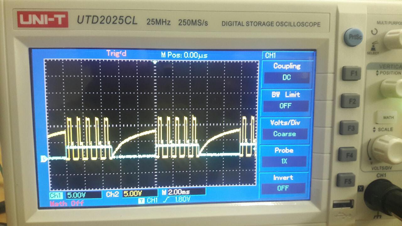
the yellow was the output and the blue is the reset while pwm is high.

the unrecognized is the output  when the reset is zero why it is getting this curve.

the last thing I run the drv8312 and the TMDSCNCD28069ISO control card with the ti DRV8312GUIv5  I run the motor and noticed that:

-the pwm signal is mapped to reset pins of drv

-and the 1 and zero sequence is applied to pwm of the drv

the yellow is the pwm and the blue is the reset.

and I can't understand that why and I noticed also the back emf on the output pins maximum volt is 12 while I run the pvdd by 24 volts from the adapter.


so that I need to know what is the level of back emf to know the commutation  or to ensure the the information that I have it's the dc us voltage/2.


I need your support to be able to drive the motor and understand why this unexpected decaying volt appearing on the emf/output

and understand the correct sequence to drive the motor with drv8332/8312 and the correct level and considerations of back emf .

and the idea of the sequence that ti used to drive the motor in control card.

Thanks in Advance.

  • Hello Amin,

    Thanks for your question.

    The first thing that I wanted to figure out is are you driving the motor in open loop? Are you blindly applying the above PWM waveform without estimating where the rotor position is? If you do not know where the rotor is and apply the above sequence, then the motor will not spin correctly or at all. The proper sequence for sensorless BLDC motor operation is: 1) align rotor to known position, 2) open loop acceleration to target speed, 3) closed loop operation at speed with sensorless position feedback.

    It sounds like your inputs are swapped - the PWM should go to the PWM input while the 1 and zero sequence should be applied to the RESET pins. Can you swap the mapping of these GPIOs?

    The voltage measured on any motor terminal that is not being driven will float at VM/2 = 12V. The back-EMF signal will be present on top of VM/2. If your motor is not spinning, I would not expect to see any back-EMF.

    You can see our motor drive software examples in ControlSuite: https://www.ti.com/tool/CONTROLSUITE

    Here is some relevant training material: TI Precision Labs - Motor Drivers: Sensored vs. Sensorless Control

    Thanks,

    Matt

  • thanks for your response,

    first thing I drive the motor in a closed loop the first thing is to align the motor in  a proper potions and sensing the back emf to ensure the alignment is done

    the applying the correct pwm in every commutation when sensing the back emf.

    and I drive the motor in a closed loop using the back emf sensing  (zero crossing) using adc.

    the second thing is the mapping of inputs.

    "the dio 0 to pwm A , the dio 1 to pwm B ,the dio 3 to pwm c and dio 6 to reset A, dio 7 to reset B, dio 8 to reset C." as I mentined

    as I mention this is the same to data sheet after alignment

    when swap the mapping I got the same response in the motor.

    do you mean the high frequency mapped to the pwm and the low frequency mapped to the reset?or viceversa

    the third is the back emf although I connect the motor or not I got that curve in he signal

    that floating  volt  will affect the bmf or not or it will occur or not?

    I don't know what is the problem is till now?

    and if every thing is correct and the motor is spinning what is the expected shape of the emf on output and is the expected commutation will occur when pmf=dc bus voltage/2  is that correct or not?

    thanks sir for your response I'll  check all that you've mentioned

    and I,m looking forward to hearing some answers and clarifications for my inquiries.

    Amin

  • Hi Amin,

    I had an idea:

    I think you have some inputs mixed up. Based on your waveform above it looks like DIO0/DIO1 are an INHA and INLA pair - this is the classical 6x PWM mode where the INHx controls the high-side MOSFET and the INLx controls the low-side MOSFET. DRV8312 is 3x PWM mode which is different. One pin controls if the 1/2-H is enabled or disabled (nRESET_x - this is the low frequency input) and the other pin controls the state of the output high or low (PWM_x, this is the high frequency input).

    Therefore:

    • INHA - DIO0   --> PWM_A
    • ENA - DIO6    --> nRESET_A
    • INHB - DIO2  --> PWM_B
    • ENB - DIO7   --> nRESET_B
    • INHC - DIO4 --> PWM_C
    • ENC - DIO8  --> nRESET_C

    This is different from what you stated earlier "the dio 0 to pwm A , the dio 1 to pwm B ,the dio 3 to pwm c and dio 6 to reset A, dio 7 to reset B, dio 8 to reset C."

    Question: that floating  volt  will affect the bmf or not or it will occur or not?

    --> back-EMF will always be superimposed on top of VM/2 on the phase. Normally you need to wait for current in the phase to decay to zero before measuring the back-EMF, because the phase voltage on the output is equal to VM/2 + I*R +VBEMF.

    --> Your commutation scheme should be looking to measure when the VBEMF is zero (we call this the back-EMF zero crossing), because that is the commutation signal occurs.

    Thanks,

    Matt

  • Thanks Matt,

    -You are correct I was wrong to describe what I'm actually connecting on hardware,I'm sorry for confusion.

    I'm actually using:

    • INHA - DIO0   --> PWM_A
    • ENA - DIO6    --> nRESET_A
    • INHB - DIO2  --> PWM_B
    • ENB - DIO7   --> nRESET_B
    • INHC - DIO4 --> PWM_C
    • ENC - DIO8  --> nRESET_C

    as you described.

    and for now I think my inputs are correct.

    my issue is that I replace the 6 mosfets and the GDU with the drv8332

    I think is the issue now the back emf sensing will differ because "back-EMF will always be superimposed on top of VM/2 on the phase." as you said and this is the thing that I didn't consider in my firmware so will take in consideration and will give you a feedback.

    thanks for your time.

  • Hi Amin,

    The video TI Precision Labs - Motor Drivers: Sensored vs. Sensorless Control should have some detail on how to detect Back-EMF.

    Let me know if you have further questions.

    Thanks,

    Matt