


Other Parts Discussed in Thread: DRV8312
Dear Support team I'm working with DRv8332 and DRV8312 evaluation KIT on sensoreless BLDC application :
I have issue that my system working with some motor and not working properly with other motors. It seems the motor parameters are effecting the system and the firmware,
is the reason (open loop stage OR PI controller parameters OR the fake zero crossings BEMF )
I need your advice regarding the best practice for tuning the necessary parameters that suits different motors, if any, or some guidelines to deal with this inconsistency.
(2) the second question: do I need to change some parameters in the firmware every time I have a new motor or it can be generic to all the BLDC motors?
....
The system i m using has NXP S12ZVMC12EVBCAN Controller, with level shifter to Match 3.3 to 5v of nxp
Motors currently being tested are the one used with the drv kit ( DT4260-24-055-04) and a similar one (but not identical) used with NXP kit (Linix 45ZWN24-90).
Thank you
Amin Zaky
Design engineer


Dear Matt,
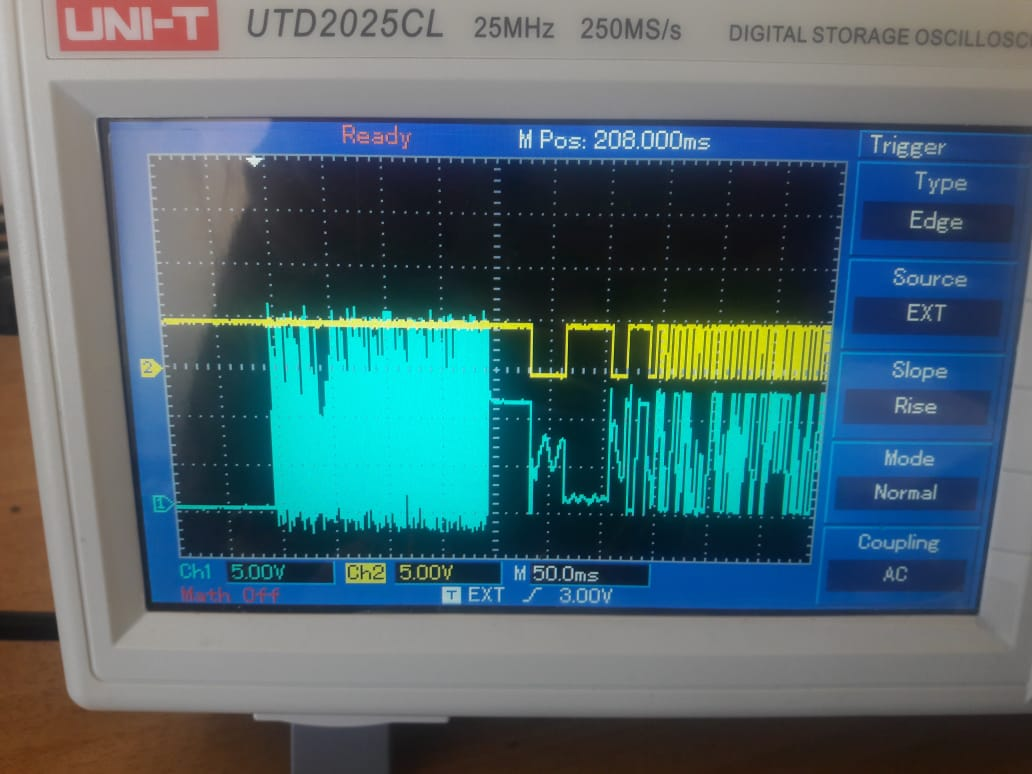
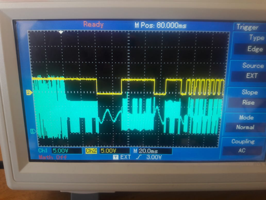
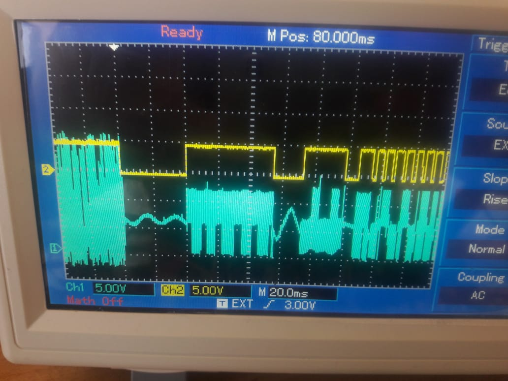
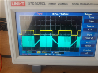
That's the result that I got from tracing the signals of reset and the output signals
1-on the the motor which working properly
2-on the the motor which didn't work
stages:
-alignment
-open loop
-closed loop the MC1v5 and the .
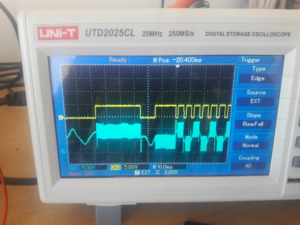
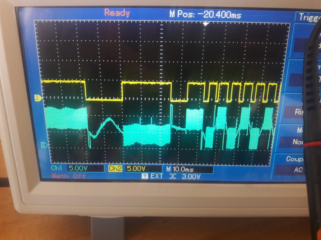
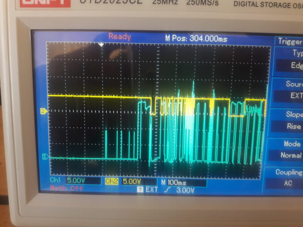
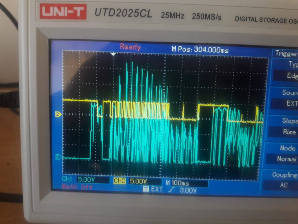
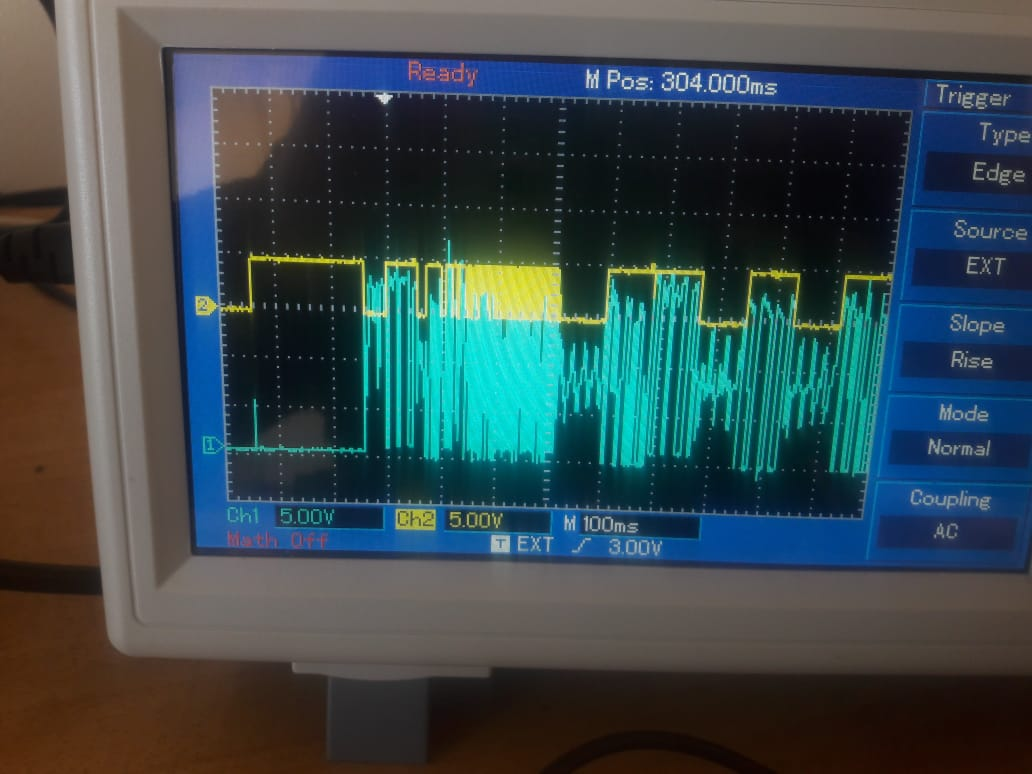
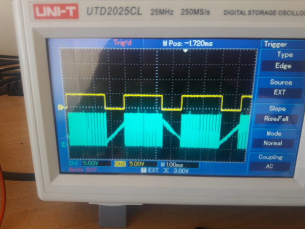
the reset is the yellow signal and the phase output is the blue signal (resrt and output of the phase)
these 3 images are the output of reset and output of working motor and the cursor is in the beginning of alignment stage.
these are the same signals on the not working motor
these 3 images are the output of reset and output of the working motor and the cursor is in the beginning of open loop stage.
these are the same signals on the not working setup
these 3 images are the output of reset and output of the working motor and the cursor is in the beginning of closed loop stage.
these are the same signals on the not working setup
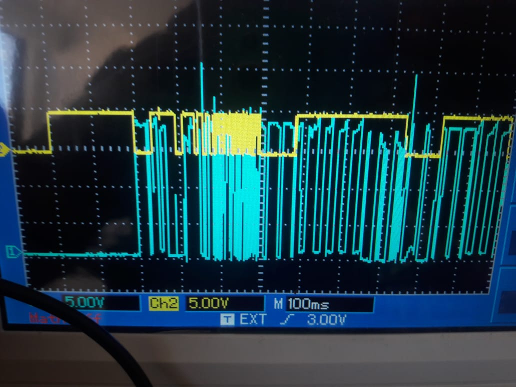
-all phases are A,B,C respectively
there is another images for commutation sequence on bipolar on the workingsystem
I think this signals would help to have a good respectve.
Thanks Matt,
looking forward to hearing from you.
Amin Zaky