This thread has been locked.

If you have a related question, please click the "Ask a related question" button in the top right corner. The newly created question will be automatically linked to this question.

DRV8343H-Q1EVM: Unexpected Insertion Loss

Part Number: DRV8343H-Q1EVM

Hello Guys,

Good day.

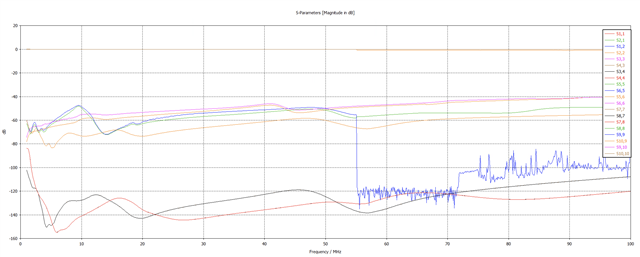
My customer is testing and simulating the insertion loss of the TI DRV8343X-Q1EVM board input filter. It appears the insertion loss on the board doesn't match what is expected of the circuit. He is sure the circuit is correct because he simulated the raw circuit elements and they behaved as predicted. When he connected a VNA to the input side of the filter before the inductor L1 and output side after the inductor L1 what he is getting doesn't make sense. It seems like the inductor is not populated on the board even though the part is there.

The measure loss does not match the expected loss with the inductor being present. Only removal of the inductor does the expected (simulated) loss match the measure loss. Any thoughts on this?

I might direct the customer directly to this thread for him to better explain his use case.

Thanks!

Art

  • Hi Art,

    Thank you for your post! I will take a look at it some more on Monday and then try to reply back to you in a couple days. If the customer has any additional information that they would like to share that might help in better understanding the problem feel free to add that to this post. 

    Have a great weekend,

    Anthony 

  • Hi Art,


    I hope you had a great weekend!


    What are the customer’s intentions for understanding the insertion loss of the power supply filter? For example: is it because the customer is experiencing unexpected high frequency noise on the power supply and they are trying to figure out why it is not being filtered out? Or do they have noise attenuation requirements at certain frequencies that they are trying to meet for their design?


    Would you be able to provide the data from the customer that they used to perform their calculations for the insertion loss? If they have any waveforms or measured data that they could provide that would be helpful to see what is going on.


    Regards,


    Anthony

  • Hi Anthony,

    I am trying to correlate board level simulations of the input filter with measurements of the insertion loss between the input and output of the filter. I would like the insertion losses to match so I can correlate measurements and simulations before proceeding into a time domain simulations with the board for EMI. 

    Thanks,

    Madhur

  • Hi Madhur,

    Thank you for the additional background!

    Would you be able to provide the data that you used to perform the calculations for the insertion loss? If you have any waveforms or measured data that you could provide that would be helpful to see what is going on.


    Regards,


    Anthony

  • The s-parameters between 60-80 dB are measured. The simulated one is based on the circuit and is from 120 to 140 (red and black traces only).

  • This is the schematic in CST (an electromagnetic simulation tool) that lets me calculate SYZ parameters. I used this circuit to generate the red and black curves at the bottom. This circuit is strictly with lumped element s-parameter models for the capacitors from the manufacturer's website. 

  • Thanks for the waveforms! You mentioned that when you tested the insertion loss with the inductor not populated you found that the performance was similar to what you had expected if the inductor had been populated. Would you be able to provide waveforms showing that condition as well? Additionally, I noticed that the color legend has colors that repeat (for instance there are 2 black traces on the legend, S34 and S87). Is there a way to get clarification as to which color trace goes with which Sxx signal on the legend?

    Regards,

    Anthony 

  • Hi Madhur,

    Please let me know if you need further assistance on this, and if so, would you be able to provide waveforms showing the condition of the insertion loss when the inductor is not populated as well as provide labeling on the color legend of the waveforms since the colors repeat?

    Regards,

    Anthony