This thread has been locked.

If you have a related question, please click the "Ask a related question" button in the top right corner. The newly created question will be automatically linked to this question.

DRV8825: Vref values higher than calculations and squeaking issue

Part Number: DRV8825
Other Parts Discussed in Thread: DRV8434, DRV8424

Greetings,

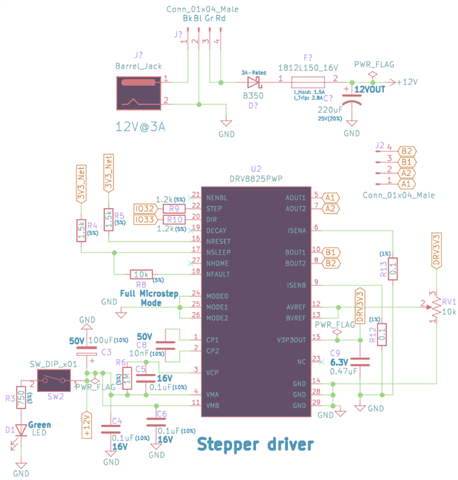
I'm intending to drive a 28HB30-402A stepper motor (Current phase: 1.0A --- Resistance phase: 2.4ohm --- Inductance phase: 1.8mH) with a drv8825 driver supplied by a 12V @3A (schematics attached); according to the current regulation guideline (Datasheet p19), with a sense resistor value of (0.1ohm) and my motor peak current, Vref (5 x Rsense x IFS) should be adjusted on somewhere around ~0.5V and considering the (71/100)% current limit in full-step mode this could roughly get to ~0.7V (please correct me if I'm wrong). My problem is using the trimmer and adjusting the Vref on anywhere below 1.2V results in stepper motor to vibrate (no rotations) and squeaking, and above 1.2V stepper rotates but squeaking remains...still, 1.2V for Vref is way higher than the calculations and I'm wondering if I've missed something in my circuit design. Your feedback is greatly appreciated.

Regards,

Amin

  • Hi Amin,

    The noise may come from motor resonance.

    Does the noise appear at one speed or different speeds?

    Can you describe how you start your motor and what speeds do you use, do you use some speed ramp or

    just start motor with final speed(frequency).

    If you could measure with an oscilloscope and current probe motor current (one of the phases) it would

    help a lot to analyze your problem.

    For low motor speeds microstepping may be a better option than full step mode.

    Regards,

    Grzegorz

  • Hi amin,

    Thank you for posting to the forum.

    I agree with Grzegorz that the noise can come from resonance. Can you please provide answers to Grzegorz questions.

    The decay mode is set to mixed decay on your schematic, have you tried configuring to slow decay? sometimes fast decay and/or mixed decay can have high ripples on the current which can cause noise. Also, what is the PWM frequency?

  •  

    My sincere apologies for the delay, I haven't had access to my bench yesterday, and thanks very much for following this,

    Regarding your questions: I've tested the setup in both step-wise (single frequency) and ramp-wise modes (a ramp of frequencies forming a bell-shaped profile, gradually increasing from 128 up to 2048Hz and then decreasing back to 128Hz), here what I observed:

    The step-wise mode requires Vref (1.2V) and below that just vibrations and no rotation movements, and above 1.2V loud noise as I previously mentioned.

    In the ramp-wise mode, the Vref voltage now makes sense because I see rotational movement at around ~0.7V, however, I still have that loud annoying noise. This sound goes quiet when the Vref is adjusted on lower values (below 0.35V), however, the stepper won't initialize the rotation at this voltage in the next run.

    (I didn't see any significant changes in results by varying the duty-cycles, 50% was the default value)

    Unfortunately at the moment, I don't have access to current probes to provide more information regarding the current profile.

    Regarding the micro-stepping and decay, since the board have already been designed and printed for full-step mode (Mode0-2 pins were all grounded) and mixed decay (pin flaoted) it's a bit hard to change the status of the pins (I'll have a look again)...

    Since you haven't mentioned any required changes in the schematics, should I be assuming the circuit design is fine?

    I appreciate your valuable feedback,

    Regards,

    Amin

  • Hi Amin,

    Thanks for your answer.

    In case of schematics I would increase voltage of C4,C5 and C6 to 25V (MLCCs lose their capacitance with 

    increased voltage).

    If you can confirm that 2048hz means 2048 pulses per second (2048 rising edges on STEP input).

    To verify current regulation if you can set Vref to 0.7V, stop giving impulses to STEP input (motor will

    be stopped) and measure amplitude of voltages on R12 and R13 with an oscilloscope,

    please use ground spring hook to ground oscilloscope probe (otherwise there may be a lot of switching noise present on measurements).

    If you can, please share these measurements.

    Probably we will be able also to find PWM frequency as well. Can you also check if there is still that

    noise present in these conditions.

    Once you check all above we should be able to determine if noise comes from resonance or PWM.

    Your motor has low inductance so noise can be also caused by PWM.

    What range of speeds do you need in your application?

    As a current probe you can use cheap probe like the one below, it is not very good to measure current

    at PWM frequencies but helps a lot to determine what is going with stepper motor and its driver.

    https://www.amazon.com/Hantek%C2%AE-Current-Clamp-kHz-20mA/dp/B06W2KFZLW

    Regards,

    Grzegorz

  • Amin,

    I just noticed that voltage ratings of C4, C5 and C6 are according to DRV8825 datasheet,

    so probably they are OK. I just do not like myself using MLCCs between 50 and 100%

    of their voltage rating because they lose a lot of their capacitance, especially close to 100%.

    I would rather tie R8 directly to 3.3.V not through R4.

    I do not see myself any other problems in your diagram but pcb layout can be also

    a source of problems.

    Regards,

    Grzegorz

  • Amin,

    Thank you for the information.

    In regards to the schematic, It looks good. My only suggestion is to connect the 10k ohm nFAULT pull-up resistor directly to 3.3V as Grzegorz also suggests. However, this should not be causing the issue of the motor vibration and noise.

    If the STEP frequency is 2048Hz, I think it is expected to hear some noise due to the frequency being in the low-end of the audible spectrum. Is it possible to increase the STEP frequency? You will have to adjust the microstepping setting to get the desired RPM speed. We have written an app-note, which you can find in this link, that explains the sources of noise in stepper motors and how to reduce the noise. Section 3.3.4 of the app-note explains how step frequency and resolution affect motor vibration.

  • Greetings, and thanks very much for your valuable comments,

    According to your suggestions, I have decided to re-design the board to have more control over the Micro-stepping pins and Decay pin via cap jumpers (I will also consider attaching the nFAULT pin directly to the 3V3 net in the circuitry), I'll be looking for a current probe to probe the current profile as well. At the moment, if you don't mind, I won't be closing this thread until I received the new boards, did some tests and report back to you here.

    * One thing to note though, the noise actually almost vanishes at higher frequencies around 2000 Hz and I have louder noises at lower frequencies around 400-800Hz; we really don't need high speeds, since we're using this setup in an incubation machine that samples need to be gently moved (rotated) under a specified constant temperature for a certain amount of time (20-60 minutes usually) and then based on the number of samples on each chip stepper will be again gently rotated to specific positions for sampling. So I might be setting the highest frequency at even 1024 Hz and perhaps that would be enough speed to fulfil our cause, however, I still need to find out where that noise come from before presenting it to others...

    Thanks very much and I'll get back to you as soon as I have an update on the new design, 

    Regards,

    Amin.

  • Hi Amin,

    Making a new board with more futures is a good step.

    Instead of using DRV8825 you may consider one of new TI stepper drivers like DRV8434 / DRV8424.

    They have smart tune function which can decrease vibrations, do not need sense resistors (no problems with

    parasitic inductances of sense resistors and their traces), though they are quite new while DRV825 is a proved solution.

    Myself, before I go to the next version of PCB I try to use the previous version as much as I can. I try to find

    as many problems as I can and try to resolve them.

    From information that you provided I can only guess your motor will be working probably below mid range instability area

    (resonances of medium frequencies) what will eliminate a few problems.

    Probably you will experience problems with low frequency resonances which can be minimized with microstepping.

    Regards,

    Grzegorz

  • One more thing. DRV8434 / DRV8424 have minimum PWM OFF time of 7 us that may

    be useful for your low inductance motor.

    Grzegorz

  • Hi Grzegorz, 

    I reckon as you suggested, considering the micro-stepping modes definitely worths giving a try, I'm also a bit concerned that the mixed decay may have caused the problem; I'll be definitely looking into DRV8434/DRV8424, they seem to be perfectly fitting to my purpose (low voltage and low peak-current stepper), thanks heaps.

    Cheers, 

    Amin

  • Amin,

    I agree with Grzegorz suggestion. You can read this application brief to learn about how smart tune helps reduce motor noise and vibration.

    Let me know if you have any questions about the DRV8434/8424 or any other driver.

    I will keep this thread open. However, it will become locked after 30 days of no replies. If that happens, you can ask a new related question.

  • Sure, I'll be appreciated, I reckon that would be enough time...

    Thanks very much,

    Amin