This thread has been locked.

If you have a related question, please click the "Ask a related question" button in the top right corner. The newly created question will be automatically linked to this question.

Understanding more DRV8701.

Other Parts Discussed in Thread: DRV8701, CSD18535KCS, DRV8303

Hello,

The truth is that I get a mess understand datasheet.

I would to know that maximun voltage the DRV8701 can apply at the gates of the MOSFET my Mosfets VGmax = +-20V

The pins that go to the microcontroller nSleep (IN) ,Vref (IN) ,snSOut (Out), So (Out), nFault (Out),   How do I interpret the pins for the program?  (such as 0 and 1 or as values A / D).  

How to calculate  the IDRIVE for the mosfets IRF3805.

THX.

  • Hi Juan,

    The DRV8701 maximum Vgs is 10.5V. Please note the Vghs and Vgls specifications in the datasheet. These maximum values are when VM > 12V. When VM is below 12V, the Vgs is less.

    Can you clarify your questions about the pins to the uc? What specific questions do you have?

    Please see section 8.1.2.2.2 of the datasheet for calculating IDRIVE. The value is based on the Qgd and the desired rise time.
  • Hello,

    Sorry for the question, and I want to understand when making the design. Thanks for understanding.

    The engine used is about 1000W 36V and 35.5A Model (MY1020)
    I will use MOSFETs are 4 or 8 = CSD18535KCS
    VDS = 60V
    Rdson = 1,6mΩ
    ID (TC25 °) = 279A
    Qgd = 10.4nC

    ----- Doubts ----------
    In DRV8701 must be connected in parallel Schottky diodes for residual F.E.M. engine and not to damage the MOSFET reverse current.
    Could place each other in parallel MOSFET to reduce Rdson and ID for mosfets.

    I can put resistors the Gate of MOSFETs to ground.

    ---About Pins DRV80701 --------

    Once nFAULT, SNSOUT, SO, pins are connected to the microcontroller as the need to interpret the program, 0 (Low) and 1 (Hight) or Analog (A / D) signals.

    The SO pin 11(out)  in the program Microcontroller (in) , as I interpret this value in data sheet go to (–0.3 to 5.75V) what does it mean?

    The Input signal nSleep the microcontroller to  DRV8701 are logical (0 and 1) or analog (A / D) values.

    The input signal IN1 and IN2, here will apply the next microcontroller PWM depending on the direction of rotation of the motor (forward or backward) through a switch. .

    --- Idrive------ Resistor ¿?-------

    IDrive resistance Section 8.2.1.2.2. Where can I get the values (the Desired rise time (100ns and 300ns)?) to calculate Idrive and RIdrive if my Qgd = 10.4nC.

    IDRIVE1 = 10.4 nC / 100 ns = 104 mA

     IDRIVE2 = 10.4 nC / 300 ns = 34,6 mA

    Select IDRIVE between 104 and 35 mA Select IDRIVE as 69.3-mA source

    Requires a (RIdrive ¿…?) kΩ resistor from the IDRIVE pin to GND

    THX.

  • Whether or not you need parallel Schottky diodes will depend on the MOSFETs, the slew rate, current, and board layout (parasitics). You will need to ensure the ratings for the DRV8701 and MOSFETs are not violated. It may be best to place a footprint for these and then determine whether they are required during system testing.

    nFAULT and SNSOUT are open drain digital output (either LOW or HIGH). They require an external pull up resistor. SO is an analog output. The datasheet has more information on how the output voltage is calculated.

    nSLEEP is a digital input (LOW or HIGH)

    IN1 and IN2 are digital inputs (LOW or HIGH)

    Can you clarify what you are asking about the IDRIVE? Table 5 on page 20 provides the assocated IDRIVE setting for each resistor value.

  • Hello,

    Thank you for your understanding and patience you have with me. :))

    I could put another MOSFET in parallel. to divide Rsdon and ID.

    The PIN SO do not quite understand this output, I read the datasheet apt 7.3.4, have to do a voltage divider at 3.3V, then to make the program to microcontroller I read the entry, if SO > = 1V means there overload and have to stop the PWM, SO = 0V if everything is fine.

    Pin SNSOUT, SNSOUT = 0 (something goes wrong and stop the PWM), if SNOUT = 1 (all is well).

    PIN nFault, nFault = 0 (everything is fine), nFault = 1 (Something goes wrong and stop the PWM).

    IDRIVE selection, which will put the new mosfets are irfs7530pbf, the Mosfet CSD18535KCS not available.
    Qgd = 83nC.
    IDRIVE1 = 83 nC / 100 ns = 830 mA
    IDRIVE2 = 83 nC / 300 ns = 276 mA
    My IDrive = 415mA +/-
    RiDrive = 68K ± 5% to AVDD or 136KΩ or more. Connect Pin Idrive to AVDD with an resistor (Ridrive).
    It´s ok ¿?

    THX. a lot Good Day.
  • SO is an analog output that corresponds to the current sensed by the current shunt amplifier. This is described in the pin functions table. It is also further described on page 17 of the datasheet.

    The nFAULT and SNSOUT are described in the pin functions table.

    This IDRIVE setting looks ok.

  • Hello Nick again,

    Special thanks for their patience and understanding.

    What I mean is that either it does not understand the concept, please a little more compression for my bad English.

    I just want to get it right, to make a circuit and better program.

    I would like to reply order my 5 questions.

    [1] ---------------------------------------------------------------------------------------------------------------

    When I read the table on nFault, sNSOUT (Pin Configuration and Functions) Pag. 4 Apto.5

    nFault / SNSOUT,

    In nFault
    In = 0 (Fault)
       = 1 (all OK)
    if it is = 0 I have to stop the PWM of the IN1 and IN2?

    In sNSOUT = 0 (Fault)
                      = 1 (all OK)
    if it is = 0 I have to stop the PWM of the IN1 and IN2?

    [2]---------------------------------------------------------------------------------------------------------------

    IDRIVE yesterday calculate my IDrive = +/- 415mA, but in suitable table 5 (IDRIVE Pin Configuration Settings). 7.3.6
    There is no resistance to that intensity. Resistance maximum I have to put 68Kohms to AVDD (Table.6)

    or have to calculate another.

    [3]---------------------------------------------------------------------------------------------------------------

    SO, pag.17, in the apt 7.3.4.
       SO = 0V (SP and SN = 0V, all ok)
       SO> = 1V (5mA) (Something's wrong)
    When the A / D input of the microcontroller detects a voltage of 1V or more.
    I have to stop the PWM of the IN1 and IN2?

    RSENSE is really necessary to put in the circuit, and put SN and Sp to Earth?

    [4]---------------------------------------------------------------------------------------------------------------

    VREF, As what is the best Desires Is Current chopping for a motor operating at 36V and 35.5A, to calculate RSENSE ..

    because  the example 3A those calculated as ??

    or I put as an example 8.2.1.2.3 Chopping Current Configuration with a desired chopping current is 3 A,.

    VREF would have to be 3.05 V.
    Create a resistor divider from AVDD (4.8 V) to set VREF ≈ 3 V
    Set R2 = 3.3 kΩ; set R1 = 2 kΩ.

    [5]--------------------------------------------------------------------------------------------------------------

    The last question You never answer, if I can put another parallel MOSFETs to reduce Rdson and ID passing through the MOSFET .

    ---------------------------------------------


    Thank you, Have a happy day.

    1. Yes, nFAULT = 0 indicates a FAULT, nFAULT = 0 indicates OK. If nFAULT is asserted the driver will automatically shutdown until the FAULT is cleared. SNSOUT = 0 indicates the current level across the sense resistor has reached the trip point.
    2. You should select the setting closest to your calculation.
    3. SO is an analog output that corresponds to the current across the sense resistor. This can be monitored with an ADC to regulate the motor current. If the differential voltage between SP and SN exceeds 1V the driver will signal a over current condition. If SNSOUT and SO functions are not needed you can remove the sense resistor and connect SP and SN to GND.
    4. You will want to recalculate the VREF based on the max motor current you want to allow and the size of the sense resistor in your system.  VREF can be derived from either AVDD or DVDD.
    5. This is possible but you will need to account for the additional gate charge the DRV8701 will have to drive. You will also have to account for any miss match in the MOSFETs which may cause one to carry more current than the other or enable before the other.

  • Hello Nick again,

    Special thanks for their patience and understanding.
    See if you can put a little more attention in apt.3 (IChop), I hope you understand what I explain..
    I would like to reply order my 4 questions.

    [1]-----------------------------------------------------------------

    I can put resistors the Gate of MOSFETs to ground? (for polarize).

    [2]------------------------------------------------------------------

    IDRIVE:
    if my IDrive calculated is 415mA, this intensity is not on the table.5, Pag.20
    As you wrote me yesterday, I have to put 68KoHms to AVDD.
    Table 5 Datasheeet:
    Source Current Max = 150mA = 68K to AVDD
    Sink Current Max = 300mA = 68K to AVDD

    My Idreive
    Source Current Max = 415 mA = 68K to AVDD (It’s OK or Not) ¿?
    Sink Current Max = 830 mA = 68K to AVDD (It´s OK or Not) ¿?

    [3]----------------------------------------------------------------------

    Apt 7.3.3 Pag.16 IChop: Current Regulation.
    This part does not quite understand, but I do not need limit the start-up and stall current of the motor.
    But anyway,But, if I disable all this, the engine will suffer?

    if I decide I do not put all this.

    The Pins (SO, VREF, SP, SN) not Used.
    Then I can disable by tying VREF directly to AVDD and tying SP and SN
    to GND (pag.16) and SO output, is disabled this go to GND or need pull up/down resistor or simply do not connect.

    If I decide to put all this.

    How I know the Current chopping for a motor operating at 36V and 35.5A.
    Because the example that is in the apt 8.2.1.2.3 pag.29 , is for:
    50 mΩ Sense Resistor.
    VREF would have to be 3.05 V (assumption)
    3A chopping current (Will BE) (assumption)

    As I find my chopping current if all datasheet calculations.apt 8.2.1.2.3 is assumption?
    Because, as that is 3A and not 4A or 2A. my chopping current.!!

    [4]---------------------------------------------------------------------------------

    The Question parallel MOSFETs .
    I did not understand this part well You wrote?
    "you will need to account for the additional gate charge the DRV8701"


    Thank you, Have a happy day.
  • 1)

    I do not understand this question? Can you try to explain another way? The DRV8701 does an internal hold off resistors for the MOSFET gates.

    2)

    The DRV8701 can only source up to 150 mA and sink up to 300 mA. If you need more gate current than this you will need a different device or else tolerate the slower slew rate.

    3)

    Current limiting is not required, just an additional feature. Correct, tie VREF to AVDD, tie SP and SN to GND. SO can be left disconnected if you wish to not use.

    The datasheet numbers are just an example. If your motor is designed to operate at a MAX of 36.5 A you can use the current limiting feature to ensure the current does not go past the motor rating.

    Rsense and VREF are used to adjust Itrip. You can set Rsense and VREF to get the desired Itrip of 36.5 A. If Rsense is 4 mOhm then VREF would need to be 2.88 V. You can adjust both VREF or Rsense to modify this.

    4)

    If you parallel MOSFETs this will effectively double the amount of charge that the gate driver will need to deliver to enable or disable the MOSFETs. Think of adding capacitors in parallels and trying to charge/discharge them.

  • Hello Nick again,

    Special thanks for their patience and understanding.

    See if you can put a little more attention in apt.2 (Idrive) again, I hope you understand what I explain..
    I would like to reply order my 3 questions.


    [1]---------------------------------------------------------------------------


    Mosfet Gate to Earth:

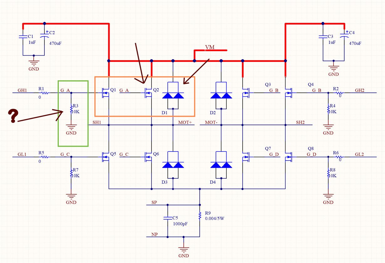
    I am sending you a photo,  you can see Gate Resistance to earth (green rectangle) .

    and the MOSFETs in parallel.

    Never I have seen parallel capacitors with mosfets.

    I put capacitors on both sides above the bridge (1uF and 470uF/60V).


    [2]-------------------------------------------------------------------------------

    IDRIVE:     About my Idrive 415mA,

    The real Rt of my Mosfet =141

     Recalculating Idrive: Idrive=Qgd/Rt    Idrive 83nC/141 = 588mA

     Well, I do not know if 150mA / 300mA is sufficient,

    What do you think??

    What would happen??

    -------------------------------------------------------

    My SELECTED MOSFET is IRFB7530PbF

    Vgs =    +-20V

    Vds=     60V

    Ids =     195A

    Rds  = 1,65 y 2 mOhms

    RDS(on) = Vgs = 10V  ID=100A

    VGS(th) = Min =2.1V   Max 3.7V

    Qg =         Typ=274nC     Max =411nC

    Qgd=         83nC

    Tr(rise time) = 141


    [3]---------------------------------------------------------------------------------------

      IChop: Current Regulation.

     I would like to know how did the calculation for 0.004Ohms Sense Resistance to 35,5A of motor and   Vref=2.88V

    Because I do not understand much formula.

     Ichop=(Vref - Voff)/(Av x Rsense)       35,5A = (?-0)/(20 x ?)

    ?= These data do not know.

     The calculated power resistor sense would be between 6 and 8W The maximum power is 5W manufacturing. Be sufficient 5W (Rsense)?


    Thank you, Have a happy day.

  • 1) The capacitance was an analogy for the capacitance of the MOSFET gate. The MOSFET gate has a parasitic capacitance that must be charged and discharged by the gate driver. Parallel MOSFETs effectively doubles the parasitic gate capacitance seen.

    2) The downside of slower slew rates will be slightly higher switching losses (aka heat dissipation). Whether this is tolerable or not will depend on the PCB heatsinking.

    3) Ichop=(Vref - Voff)/(Av x Rsense). Voff should be measured by the MCU when 0A is flowing. It is typically in the order of mV. Av is given in the electrical table as typically 20..

    Ichop = 35.5 = (2.88 - 0.02)/(20 x 0.004)

    At 35.5A, a 4mOhm resistor will dissipate 5W.

  • Hello Nick again,

    Special thanks for their patience and understanding.


    I would like to know if Texas Instruments has another driver with a Source Curren >= to 1A,  for my Idrive 588mA, And  for the characteristics of the Motor.

    I am fear that  slower slew rate and source current to not be enough for  mosfet and overheats.


    Thank you, Have a happy day.

  • Hi Juan,

    We do not have a stronger H-bridge motor gate driver.

    You could use two half-bridge drivers. http://www.ti.com/lsds/ti/power-management/half-bridge-driver-products.page

    You could also use just two half-bridges of a triple half-bridge driver. Ex. DRV8303.

  • Page 17 of the data sheet says.. " SO is only valid during forward or reverse drive". What is the SO value when the motor is not being driven?