Because of the holidays, TI E2E™ design support forum responses will be delayed from Dec. 25 through Jan. 2. Thank you for your patience.

This thread has been locked.

If you have a related question, please click the "Ask a related question" button in the top right corner. The newly created question will be automatically linked to this question.

DRV8312, nothing but FAULTs

Other Parts Discussed in Thread: DRV8312

Hello,

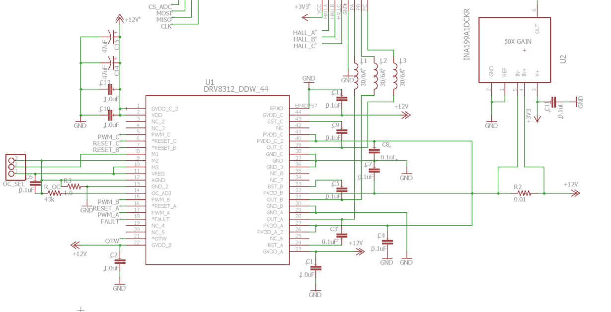
Recently produced a prototype that uses the DRV8312 to drive a sensored BLDC motor. I'm having an issue where any time I try to drive any of the motor phases, both the OTW and FAULT lines fire off immediately and disable the device. I have checked for any shorts to ground and can not locate any. The OTW fault is especially peculiar, as the device is just at room temperature. Does anyone have any ideas? Is my chip dead? This is the second one I have installed with the same issue. I've read the datasheet through several times and I can't find any issues with my schematic that would cause this behavior. These faults occur even with the load disconnected. There is 12V present on all power pins, and 3.3V at VREG. The motor does not spin at all, only a faint click before the FAULTs trip.

  • Hi Jordan,

    Have you operated the device without a motor? A small resistive load can help debug.
    What are the M2 and M1 pins set to?
    Do you have a solid connection from the PCB to the thermal pad of the device?
  • Hi Rick,

    Thank you for your reply.

    I have attempted to use the DRV8312 without the motor. Instead I have attached it to some 1kOhm resistors, however this does not change the results.

    M2 is set to AGND, M3 is set to VREG, and I have tried both configurations of M1. I am confident that the thermal pad has a solid connection to the PCB. I have installed a new chip 3 times thus far to eliminate that possibility. Are these devices particularly susceptible to heat damage during soldering? I don't believe I abused them enough during installation to cause them to totally fail. I've installed each attempt using a different method (hot plate, IR reflow oven, and hot air).

    Here is a snapshot of my situation:

    Top signal being voltage between Phase A and Phase C (1kOhm load), middle signal is RESET_A, bottom is PWM_A.

    It appears that the device is activating over-current protection prematurely. I have checked for shorts, there are none that I have been able to measure. My OC programming resistor is set to 43kOhm.

    I'm definitely scratching my head over this one. Is there a way to disable the OC protection circuitry? I suspect removing the OC programming resistor could do this, but I'd rather not do this without a thumbs up from someone who knows their stuff.

    To me it seems like its one of two things:

    1) I managed to destroy 3 seperate chips during installation

    2) I've missed a crucial design consideration

    Any input is appreciated.

    Thanks.

  • Hi Jordan,

    When is the nFAULT and nOTW asserted after PWM_A is set to a logic high?

    One item I noticed is that you set PWM_A high and left it there. This will cause the Phase A to disable as the bootstrap capacitor charge is depleted. Please refer to section 8.3.2.1 of the datasheet for details.

    I don't think you need to change the oc adjust resistor yet. If you do, you can change the resistor to 22k. This will increase the current to 11.6A.