This thread has been locked.

If you have a related question, please click the "Ask a related question" button in the top right corner. The newly created question will be automatically linked to this question.

DRV110: Small ripple in current control mode

Part Number: DRV110

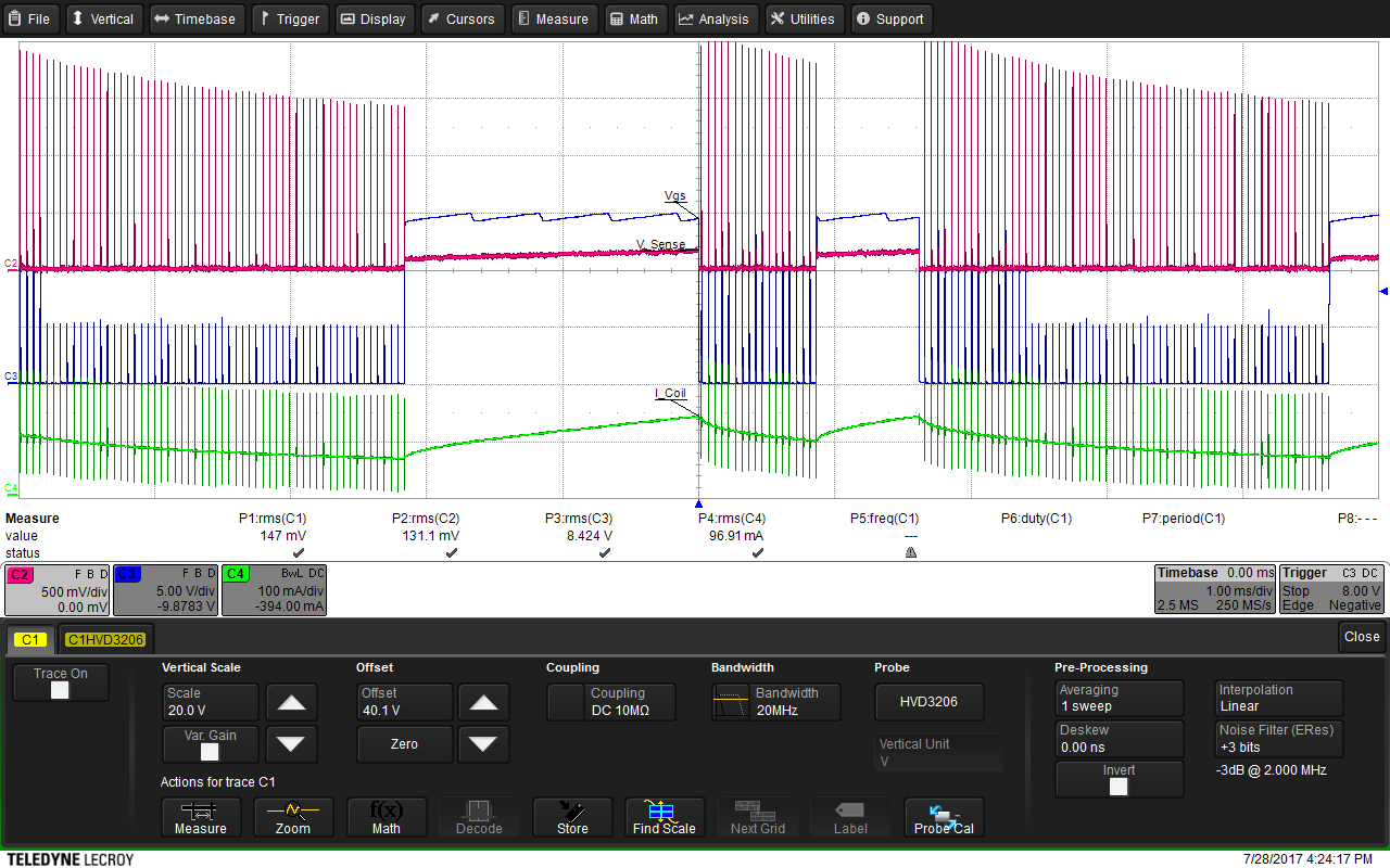
Hi, I'm designing a relay driver using DRV110.  The attached waveform is from using DRV110EVM to drive a Panasonic Relay: HE1aN-W-DC24V-Y6.

The settings on DVM are: DCsupply = 24V, Rpeak = 750k, Rhold = 255k, Rosc = 200k, Rs = 5k.

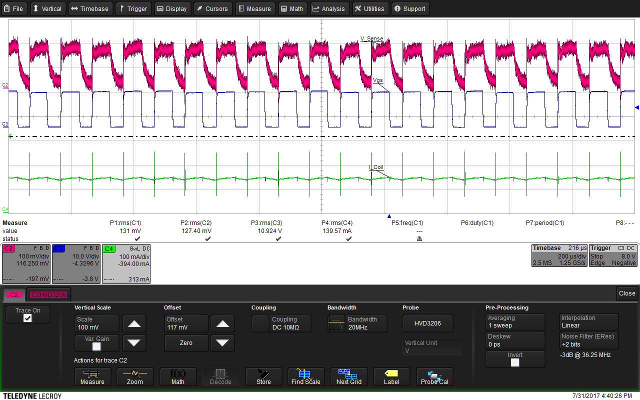
In the PWM output, we observed that there is a small pulse appears after the regualr PWM pulse. And the measured frequency is 6.6kHz, whereas the desired frequency set by Rosc should be 20kHz.

I'm wondering what causes this small pulse, and what can I do to overcome this issue.

Thank you so much!

Ji

  • Hello Ji,

    This is correct operation of the DRV110. The DRV110 is a hysteresis controller with a minimum duty cycle.

    The DRV110 SENSE pin can only sense the current while the FET is on. Because of this, the current is compared to an upper threshold during the time the FET is on. When the FET is off, the current decreases due to losses in the coil and diode as it recirculates. The FET will turn on again for at least the minimum duty cycle every PWM cycle (7.5%). Some pulses are short because the upper threshold is reached quickly during some cycles.

    If the threshold of the SENSE pin is not reached within one frequency cycle, the FET will stay on through that frequency cycle and into the next one. This is why some pulses are longer than the programmed PWM period.

    I've attached a slideshow that explains this in more detail with pictures.

    DRV110 PWM.pdf

  • Hi James,

    Thanks for your answer and the attached slides, this explanation fits well with our measurement on DRV110 EVM. 

    I'd like to ask if you know about using DRV110 with this non-uniform PWM  will cause any negative effects in overall design? For example unstable oscillation,  EMI, reducing lifetime of the IC or the relay coil.

    I'm just blind guessing here,  but it'll be very helpful if you can point out some directions.

    Thanks

    Ji

  • Hello Ji,

    The non-uniform PWM should not reduce lifetime of the relay or IC and oscillation should remain stable. As for EMI, I have not heard any complaints from customers in the past, so you should be fine.

    In my opinion, the best way to evaluate the DRV110 is to look at the current in the coil as you did above. If you are happy with the waveform (the current level is accceptable, the ripple is small enough, etc), then your design should be fine.
  • Hi James,

    I get back to work on the DRV110 circuits now.

    With our own designed PCB, I get the following waveform: 

    Zoomed-in:

    During in the time that I_Coil is decreasing, I observed multiple spikes on the waveform. Is this normal? 

    Also, it seems like the lower side of the hysteresis comparative is triggered at different level every time I_Coil decreased to its lowest value. Can you explain why is this happening?

    Thanks for your help!

    Ji

  • Hello Ji,

    I believe the voltage spikes on the sense pin are causing this behavior. The datasheet recommends putting a filter between the SENSE pin and sense resistor. I believe the DRV110EVM implements this filter too, if you want an example. Do you have a filter on your SENSE pin?

  • Hi James,

    I have a RC filter on the sense Pin as datasheet suggested:

    I used a 1k Ohm and 100pF RC initially, and then changed to 10k and 100pF. The waveform I posted earlier is captured under the second setting.

    Do you recommand to use a larger RC filter? The PWM frequency is set at 20kHz for now.

    Thanks

    Ji

  • Hello Ji,

    I think you should try a larger filter. I think I saw a problem similar to this a year ago. I believe we recommended 1 kOhm resistor and a 2.2 nF or 220 nF capacitor.

    In the waveform you sent me last week, is the SENSE voltage trace measuring the SENSE pin or the sense resistor?

  • Hi James,

    Thanks for your advice, I'll try the new filter setting in a moment.
    The V_Sense is measuring the voltage on the sense resistor, I will try to get a measurement at the SENSE pin this time.

    Thanks
    Ji
  • Hi James,

    By changing the RC filter and measure voltage on the SENSE pin, I get much cleaner V_sense now.

    The ripple current on the inductor is still much larger than what I measured using the DRV110EVM with the exactly same relay. It looks like the internal comparator's threshold is keeping changing within some boundary. Is this expected?

    Thanks

    Ji

  • Ji,

    Can you please send me your schematic with the DRV110?

    There must be some important differences between your schematic/layout and the DRV110EVM since your results are so different.
  • Hi James,

    I increased the RC filter value again to R = 1k, C = 10nF. And now the waveform looks normal now.

    Thanks very much for your help!

    Ji