This thread has been locked.

If you have a related question, please click the "Ask a related question" button in the top right corner. The newly created question will be automatically linked to this question.

DRV8323: DRV8323 gate signal connection(GHx, GLx) ??

Part Number: DRV8323
Other Parts Discussed in Thread: TIDA-00774

Hi,

I designed the motor driver using DRV8323RH.

BOOSTXL-DRV8323RH circuit was referenced.

But I have a trouble in switching noise. So, I tried to shorten the path(GHx, GLx) from MCU to DRV8323.

And I use slow turn on time using low IDRVE.

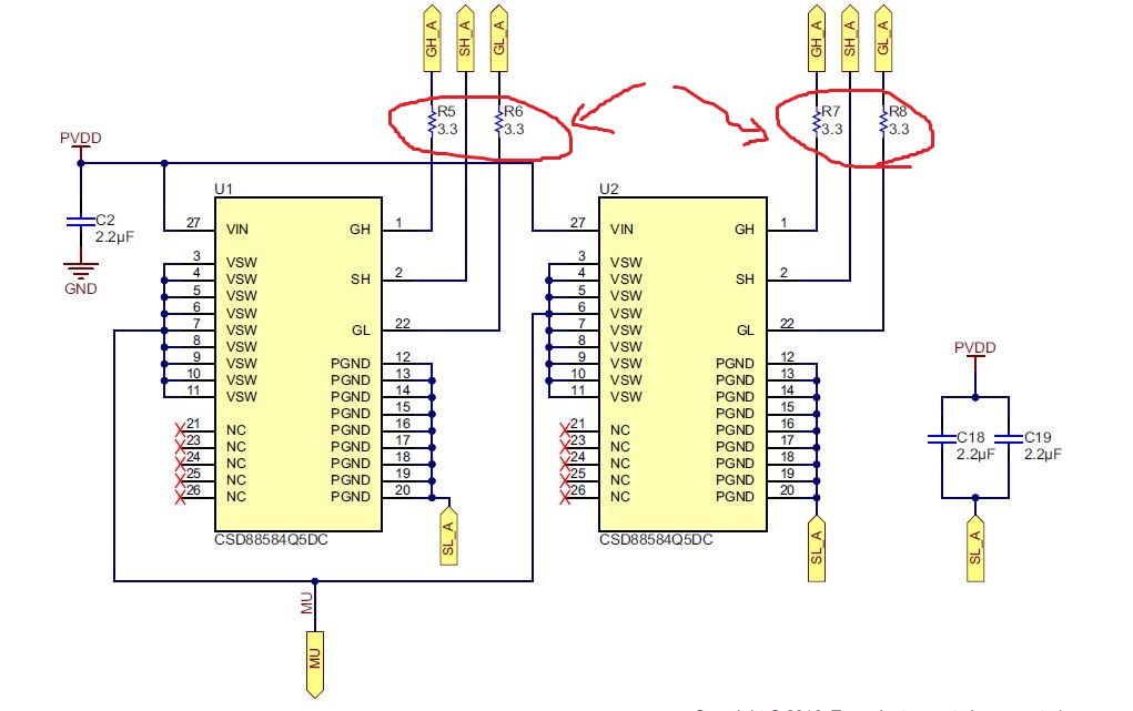
Recently, I found the resistor in GHx, GLx path in TIDA-00774 18V/1kW circuit(below figure)

What is the role of resistor?

Can it reduce the switching noise in fast turn on time?

  • Hello Min-su,

    This resistor is meant to limit the current into the gate of the FET, but the IDRIVE settings can also do that. The TI Design demonstrates both options which can be used to reduce turn-on time.

    Reducing trace length between the DRV8323 and the FETs should also help parasitic inductance. Vias can also add parasitic inductance in the path, so trying to reduce the number of times the gate drive signal or other power signals change layers will help to reduce parasitics. The FET package and bond wires can also add inductance, which may also cause ringing.
  • Thnak you, James.

    I have designed the board to shorten the trace form DRV8323 and MOSFET.

    But, I had a trouble in switching noise. So, I used low IDRIVE condition.

    Can I have one more question?

    What is better design in a view point of trace from DRV8323 to MOSFET.

    1. short trace(maybe 25mm) with via.

    2. long trace(maybe 40mm or over) without via

    Thank you.

  • Hi Min-su,

    That's difficult for me to say. There are books on PCB design that could probably give you a good recommendation. I would probably choose the 25 mm trace with the via personally.

    If changing the IDRIVE setting doesn't help, you may want to consider adding an RC snubber circuit on the switch nodes to reduce the noise on the switch node further. You could also consider put ferrite beads on the switch node before your connector to the motor so the high-frequency signals don't propagate to the motor wires. Also, you could put a ferrite bead on the motor wires after the connector too.
  • Thank you for answer, James.

    It will helpful for me.