This thread has been locked.

If you have a related question, please click the "Ask a related question" button in the top right corner. The newly created question will be automatically linked to this question.

DRV10987: drv10987

Part Number: DRV10987

hi,

i am working on drv10987 , i am facing problem in alignment of bldc motor. It takes more time to align , even i have set 0.04 s in align time in gui,motor spec is 24V BLDC ,1.24(Rphase), 412(mV/hZ),A1=0.019Hz/s,A2=0.22Hz/s2

please help in this regard

  • Hey Meghana,

    The align time is just the amount of time you are setting the DRV10987 to send current to try to align the motor. Setting that parameter doesnt mean that the motor itself will align in that time.

    Is the problem that the DRV10987 tries to align the motor longer than 0.04s?
    If so, please give a scope capture of one of the phase currents proving that this happens.

    Or is the problem that even though you set the align time to 0.04s, the motor itself doesn't align in that time?
    If this is the problem, then either increase the "open loop/align current" setting to drive more current, or you'll have to increase the align time.

    Let me know if this answered your question, and if so, please press the resolved button.

    Sincerely,
    Sanmesh U.
  • Hi Sir, sorry for the delay in reply

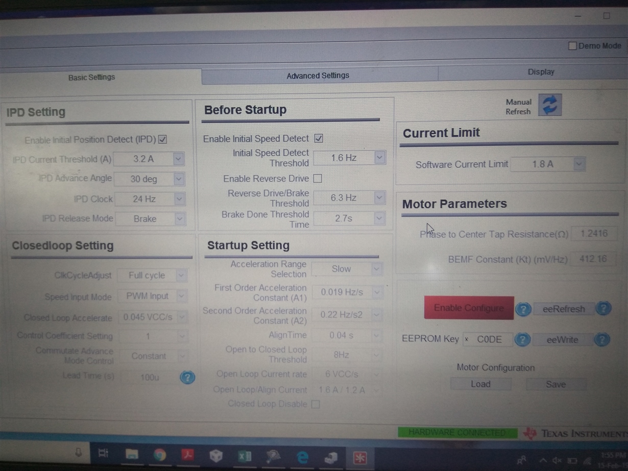
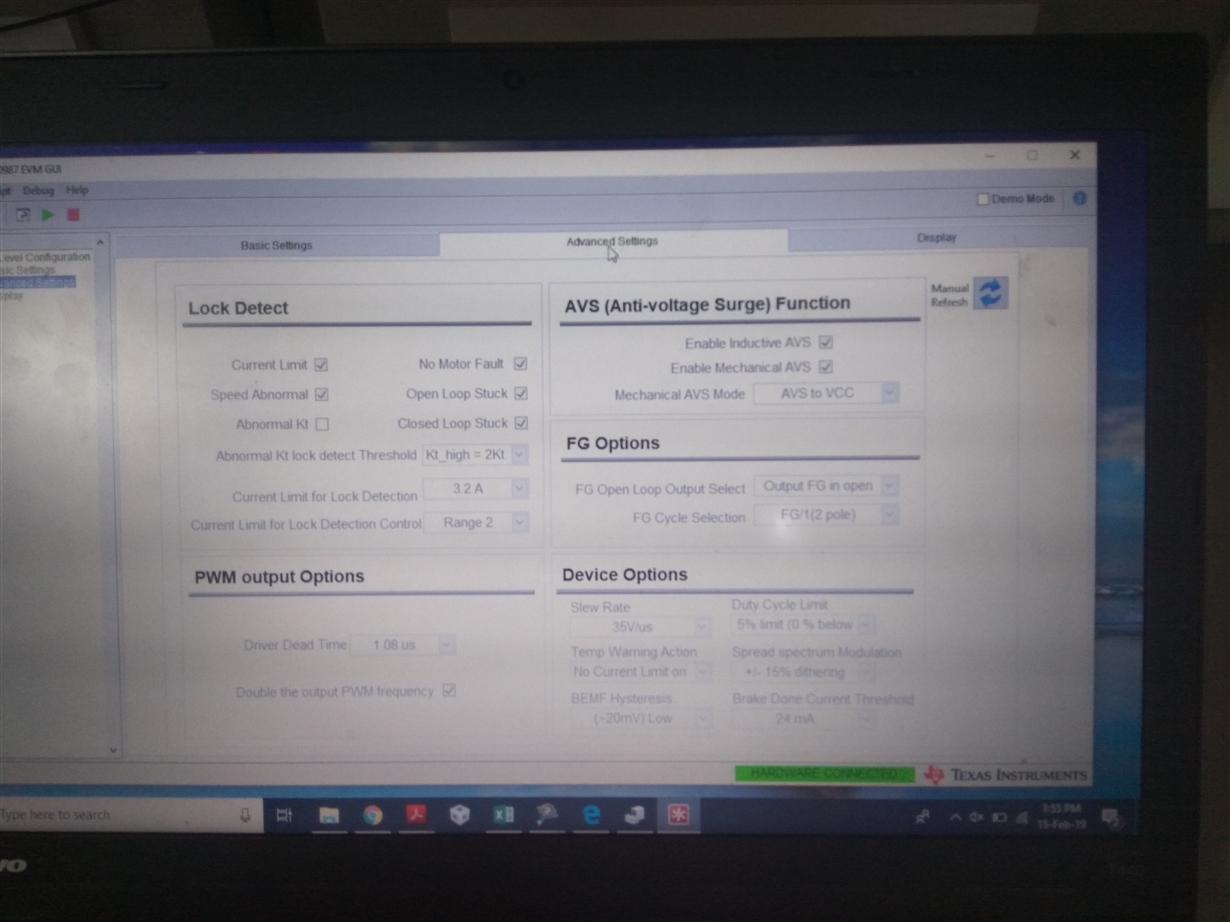
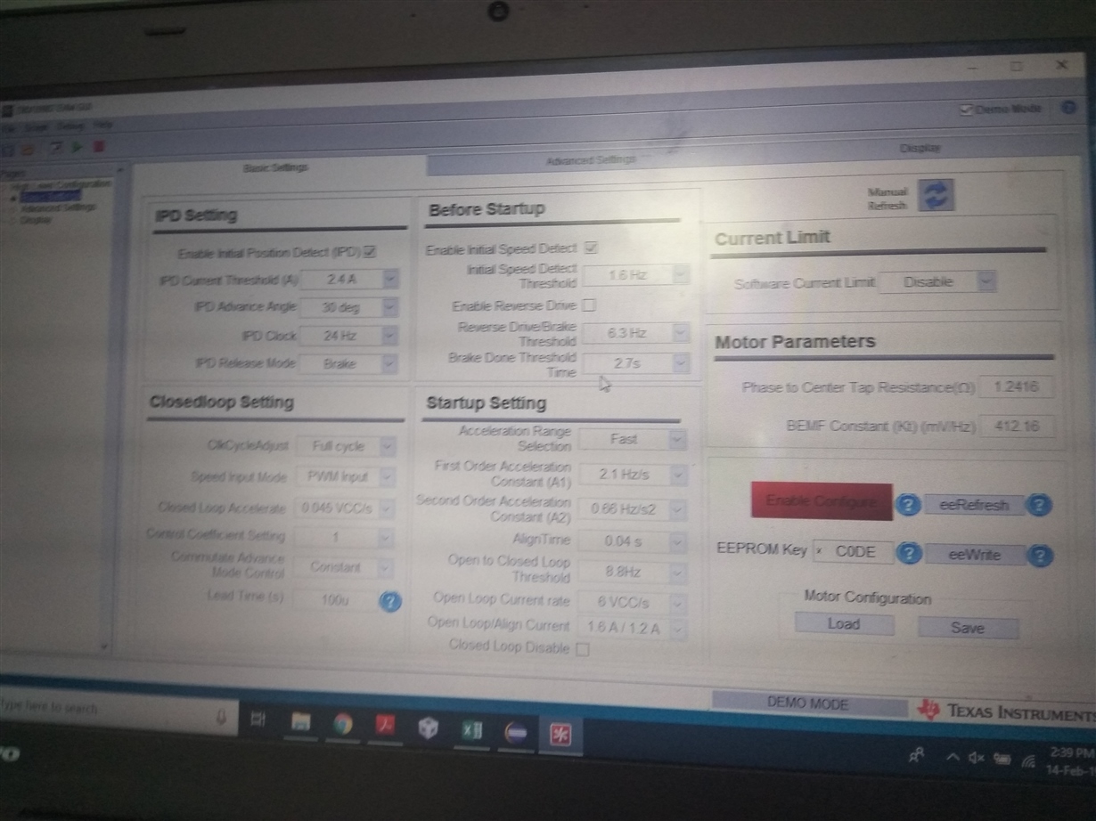
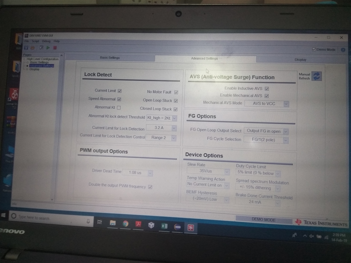
    open-loop/align time is set to max, still, issue not solved. The issue is if I set acceleration range selection fast and set acceleration constant accordingly, the ldo of drv ic V3P3 drops, which I have connected as Vcc for my st microcontroller through which i am giving my speed PWM command. And I would also like to know the relation between speed and duty because when i am testing for some period it gives linear relation and reached a constant speed for the same incremental duty ratio. I will share my gui setting, please let me know if I am going wrong somewhere.

    THANKS

    Meghana

  • for all PWM duty the fan runs very smoothly, only the issue is with alignment, sometimes it does not start at all... for the first time switching. until a push through the hand.

       ... if acceleration is set fast, seems like draws more current and goes to current protection, and v3p3 drops

    Thanks!

    Meghana

  • Hey Meghana,

    1) Because you have enabled "Initial Position Detect" IPD, the DRV10987 won't do align and go. Instead it will start driving from the position it is in. That is why you dont see an align and go. To learn more about IPD and align and go, please refer to the datasheet. Please decide whether you want to do align and go or IPD. We also have an IPD tuning guide www.ti.com/.../slou426a.pdf
    2) Speed is correlated to duty cycle. The actual relationship depends on the mechanical load. You say that when you increase the duty cycle, the speed doesnt increase. This could be because of the "software current limit" which limits the actual duty cycle applied so that the current limit isnt exceeded. You can check this by seeing if the "speed cmd buffer" does not equal "speed cmd"

    Let me know if this answers your questions.
  • hi Sir, in order to avoid the initial reverse rotation, I am enabling the ipd settings, still at some duty, the 3.3V Of DRV IC drops to 1.4 volt which resets the ST microcontroller which I am programming (duty cycle) as speed command. Actually what settings in GUI is exactly the reason for this V3P3  to drop?

  • Nothing in the GUI that should directly cause the V3P3 to drop. The only thing to cause V3P3 to drop is:
    1) if there is load current above the electrical spec. Max current draw when step-down regulator is in buckmode is 20mA. If step-down regulator is in linear mode, then you cant put a load on V3P3.
    2) Make sure Vreg also isnt going down below electrical spec. Vreg can affect V3P3 because it powers V3P3.
    3)Please make sure there is nothing in your circuit that could cause V3P3 or Vreg to draw more than electrical spec

    Can you describe in more detail what condition that 3.3V LDO drops? Once the device goes past a certain speed? and does Vreg also drop? Does any faults happen?
  • Hi Sir, as per your suggestion I am now working with align and go method, now that dropping of V3P3 is not happening, it was happening only if I use IPD setting, as i have shown in image of my last post  but at each start, it goes anticlockwise and starts in the clockwise direction,...currently i have set open loop/to align time to maximum 1.6A/1.2A, and align time 0.04sec, with slow acceleration range 0.019Hz/s and 0.22Hz/s2.   

    do I need to change open loop/align time ratio to the minimum value, to resolve this issue...its like in align and go it now takes some 3.36 sec to start.

    Or any other setting I need to change.. currently, I disabled, initial speed detect and enable reverse drive and set to no brake......which makes my BLDC  fan  to stop slowly

    Thanks

    R MEGHANA

  • I just want to confirm what problem we are solving.

    Are we solving problem of motor when aligning it spins anticlockwise first, then clockwise?
    If so, then in align and go, you cant guarantee which direction the motor will align first.

    Or are we solving the problem of startup taking too long?
    You can set align time to the minimum, but then you need to make sure open loop/align current is as high as possible to make sure you are able to align in the time. If you want to cut on time, you should try to increase the open loop acceleration rates and closed loop accerlation rates.
  • Hi Sir, during alignment mode Vreg is dipping with IPD enabled, we are using Vreg to power up ST MICROCONTROLLER , BUZZER , AND IR SENSOR by using 5V(taken from DRV Vreg pin) TO 3.3 regulator.
    My doubt is why this happens, is it related to GUI(fault lock protection ) Setting or any external hardware
    Please let me know regarding this issue.
    Thanks
    R Meghana
  • What may be happening is that when doing IPD, the inductance is so small that a high current spike is drawn very quickly and our voltage drops on the Vreg.
    Either the inductance is too small on the motor, or lower the IPD Current Threshold.
    For other suggestions in tuning IPD, I would follow this IPD tuning guide www.ti.com/.../slou426a.pdf .
  • Hello Sir,

    Actually in TEXAS DRV10987 EVALUAITON BOARD  dropping of Vreg 5V  is not happening, it happens in my bldc board , i have even changed the ipd current threshold value, but still i could see the dropping of Vreg if i enable IPD, (Rph-ph=2.56 ohms, Lph-ph=8.13 mH(LCR METER MEASURED ),pwm at speed pin (15khz)....I have tuned according to ipd tuning guide, these parameters are IPD BASED, not align n go, but still could not resolve.

    only if i disasble IPD, Vreg doesnot drops but the performance of fan is not good at start it turns back n forth n starts....

    i will share the image of my bldc hardware schem...let me know if anything we are going wrong

    Thanks !

    Meghana

  • Hi Sir, now what i have done is Vreg is isolated from the microcontroller, and i am connecting load 80mA (R load 65 ohms)  across 10uF CAPeven though (100mA is capable it should be capable to load maximum) , IN BUCK mode, motor aligns and stops.

    If Vreg is isolated, if nothing is connected to this pin it works properly, so what can be the problem is it still tuning.

    Thanks!

    Meghana

  • So your saying when vreg is not connected to a microcontroller but instead to a 80mA load, the motor aligns and then stops, instead of align and go. Is there any faults hitting like overcurrent?
  • yes Sir, 

    In evaluation board, it runs proper,as in evaluation board nothing is connected to Vreg pin. and here it does not shows any OVERCURRENT FAULT

    But in my hardware, i am connecting a regulator from Vreg to step down voltage to 3.3v to give to ST microcontroller, in such connection 5v at Vreg drops.

    In order to verify this issue, i have isolated all my connection to Vreg, it works proper .....

    but Vreg is capable to load 100mA as per datasheet, so i connected 80mA, resistor in buck mode as load, it drops still...., is it like we should not connect any load to this pin......And in standby mode vreg is resposible for vp3p and v1p8.... so again im connecting a regulator from this vreg pin externally....is this created the problem

     if there is OC fault, what parameter is reason for this,........

  • Hi Sir, with ti evaluation board ipd enabled , i am able to see 4.47 sec it takes to start( seeing the motor running),.....is it the best performance or can we still reduce this time, i would like to know the best time that can be achieved with this ic drv10987 , ipd enabled upto now
    Also its like if ipd disabled i can see the motor start aligning and going at 3.36 sec...
    So, i would like to know what i have tuned is the best performance with this ic , or still we can achieve more
  • Let me answer you on monday
  • 1) In your schematic, you have the Vreg pin connected to the output of the external regulator, which I dont think makes sense. If you are trying to step down the Vreg 5V to 3.3V, you need to put the 5V to the input of the external regulator. You also have the external regulator input to V1P8 which I dont think makes sense either
    2) Although the average current of the external regulator might be lower than 100mA, the peak currents might be higher, which our Vreg can not supply. I would rather you either use our V3P3 3.3V supply which gives max 20mA or use an external regulator with input power source your 24V supply.
    3)I dont think IPD should take 4.47s. Please make sure no faults are hitting that are causing it to restart everytime.
  • thankyou Sir for helping me in solving this issue . Ya Sir 1) was actually errrror in schematic that i have corrected already, AND i will check with 2) i.e. i will use v3p3 to directly supply the external microcontroller.
    And i couldnot see any fault hitting in gui ,and i would like to know usually how much minimum time it takes to see motor start spinning through ipd.
  • Let me check in the lab and get back to you.
  • In lab, I saw IPD times for the setting below to be 150ms.

    I think the reason why your IPD time is higher is your IPD current thresold is high. Lower it, and see the time decrease. Also increasing IPD clock will also help.