This thread has been locked.

If you have a related question, please click the "Ask a related question" button in the top right corner. The newly created question will be automatically linked to this question.

DRV10983-Q1: Lock code 0x1: current limit happen when very low speed and low current

Part Number: DRV10983-Q1
Other Parts Discussed in Thread: DRV10983, DRV10987

Hello experts,

I am using a drv10983-q1 EWM to evaluate my motor.

motor parameters: 8 poles, 3A RMS max, max speed 45 krpm (normal operation 31 krpm max for long time), R= 0.36 ~ 0.66 Ohm, L = 17 ~ 23 uH.

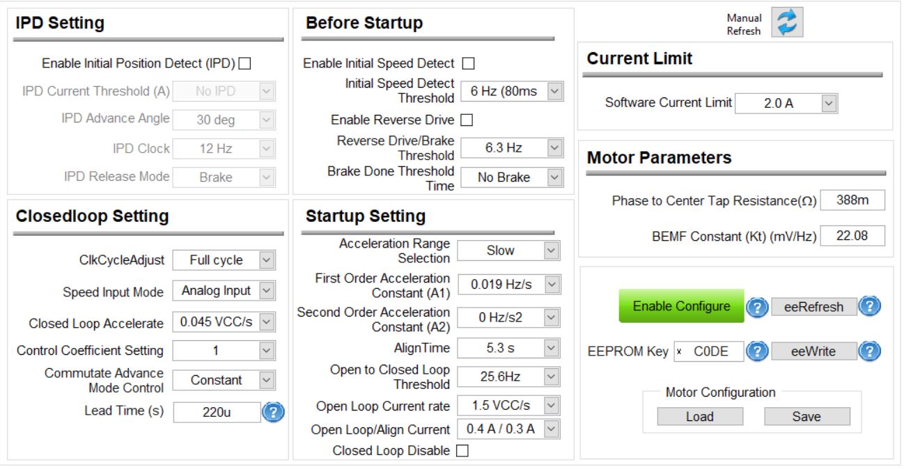
Follow by the turning guide "SLVUAV9–June 2017". I filled out the parameters: Resistance = 0.388 Ohm and Kt = 22.08 mV/Hz. FG cycle = FG/4 (8 poles); slew rate = 120V/us; driver dead time = 440 ns; double the output PWM frequency is checked; open to close loop threadhold = 128 Hz

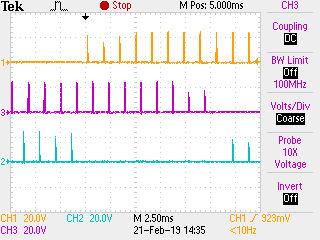
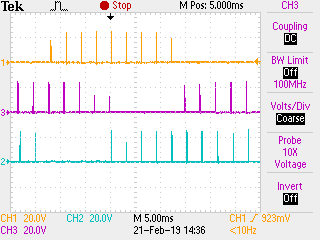
When I set the motor speed to 50Hz, the motor spinning and slowly speed up. But when reach to 35.8 Hz, the motor suddenly stop and start ramp again. Always the same phenomenon.

The lock code show 0x1 : current limit. The over current light is turned on.

When motor stop, the current measured from power supply is 180 mA, so small with the limit current 2A of the Driver.

Please help me,

Best regards

  • Hey Bui,

    1) I am assuming your current limit is happening in open loop because the fault happens at 35.8Hz, while your open to closed loop threshold speed is 128Hz. It might happen because the motor can't spin as fast as 35.8Hz at open loop. Lower the open to closed loop threshold to something like 25Hz.
    2) To monitor how much current is happening at fault, I would recommend using an oscilloscope current probe on one of the motor phases and just seeing how high it is at the current limit fault.

    Please tell me if these steps work first.

    Sincerely,
    sanmesh U.
  • Dear sanmesh U.,

    Thank you very much for your reply,

    1. Correctly as you said, when "open to close loop threshhold" is set to 25, the motor keep moving forever without a failure.

    2. Extremely sorry since I don't have current probe.

    I would expect the motor run faster. 25Hz is only 10% of the maximum speed the motor can perform. I had tried to adjust every parameters on the Evaluation GUI but nothing improved.

    Even if I can not measure the current, are there any way to improve performance of the motor?

    Your help is appreciated,

    Best regards

  • Seeing the shape of the current on the oscilloscope often tells you how well you are spinning the motor. However, if you want to improve performance of the motor without the current, there are a few things you can do:
    1) Increase Vcc. Vcc should be limited by the motor rating and the DRV10983-q1 absolute max Vcc of 28V. I see from your GUI scope you are only using 12V Vcc.
    2) In the "speed" input box in the display tab, set the max speed value of 511 to go max speed. In the device, the speed cmd set is out of 511, so if you set it to 511, you will get 100% duty cycle.
    3) Make sure your current isn;t being limited by "software current limit" in the GUI. If the "Speed Cmd Buffer %" in the GUI display tab doesn't match "Speed Cmd %", then there is something wrong.

    Try these first steps before we proceed further.
  • Hello Sanmesh,

    I tried with 24V power supply and the motor get "Over current" faster. From external monitor; only 80 mA make the EVM over current (in 12V it is 160mA)

    During operation, motor generate noise. I had tried to decrease "Driver Dead Time" from 440ns to 1us and the noise was reduced. The power consumption has also reduced.

    I can not run the motor in close loop. whenever un-tick the "Close loop disable", the motor will stop.

    I don't understand why the Over current happen in such a small current. Does that happen because of the dead time? I tried to increase dead time to 1us but the Over current still occur.

    I got a F28069M Launchpad. The motor was working well with the Lauchpad, very smooth, no noise. The PWM from the Lauchpad is 75Khz.

    I have a question: Even if I get the graph of current on Oscilloscope, what should I do for the next? Did I configure some thing wrong? Is that the driver compatible with my motor? With the characteristic of my motor like I has told, what is the driver compatible? Please introduce me.

    Thanks in advance,

    The following picture is voltage of phase U, V, W compare with GND

  • 1) • Dead time should be at least 440 ns. Putting it lower to 1ns may cause fet shorting and thus cause the overcurrent fault to happen.

    2) • Ringing is coming from spinning the motor in open loop. Once you go to closed loop, it shouldn’t ring.

    3) Lets first focus on getting to closed loop without any issues. Lets set all the accelerations to conservative parameters.

    I have attached a config file to load through the gui "Load" button". The settings are below.Please try this to see if you are able to reach closed loop. Also make sure your phase to cetner tap resistance and bemf constant are entered correctly.

    BuiPhuocE2ESettings.csv

  • Hello Sanmesh,

    Thank you for your help anyway,

    1. What I said is changing from 440 nano-second to 1 micro-second. (not to 1 nano second)

    2. I can not get in to close loop because of current limit problem. It always happens even when low speed, low acceleration settings, long dead time driver setting... Current limit is the bottle neck I should get out first. After that, I can my self handle the close loop and optimization.

    Since the Driver 10983 is an ASIC, even I enter the wrong resistance and Back EMF value, I think that it can not cause the the Current limit problem. Base on the data sheet of the motor, I fill the Resistance value. Base on instruction on the Turning guide document (SLVUAV9–June 2017), I calculated the Back EMF value. I am not sure that values are correct, but I think it can not cause Over current problem.

    Just look at the hardware, the DRV10983Q1 EWM is so simple compare with sample driver from Motor's manufacture. They may have filter and protector but DRV10983 has only driver without any external device.

    I am afraid that the problem caused by hardware. If so, it can not be fixed by just configuration.

  • 1) I think what is happening is the inductance/resistance ratio of this motor is too small for the DRV10983-q1 to spin the motor. The motor's inductance/resistance ratio = 23uH/0.39ohms = 59us. The "Recommended Application Range" of the motors our DRV10987 can drive is minimum 100us inductance/resistance ratio. If this ratio is too small, it can cause small-duration current spiking which can trigger the current fault. The duration would be so small that it wouldn't get noticed by your supply current measurement. An oscilloscope current capture would confirm this if we were able to get one.
    2) The reason why resistance and kt entered matters is that if you enter the wrong values, the DRV10983-q1 will spin the motor incorrectly which can lead to current limit lock.

    My only other suggestions/ideas would be:
    1) Does the motor look like it is spinning smoothly in open loop? If not, then you wont have a nice transition to closed loop. Please increase the "Open Loop/Align Current" so that the motor will spin more smoother with more pull
    2) Disable the current lock and just let overcurrent protection protect the IC (which has a current limit around 3.5A). Maybe this will give you more leeway in getting the motor to closed loop.

    Those would be my only ideas. As mentioned before, maybe the motor's inductance/resistance ratio of this motor is too small for our driver to spin.
  • Hey Bui,

    Is there any other follow up needed? Were you able to resolve the issue? As mentioned before, we may not be able to because of the motor's low inductance/resistance ratio.

    Sincerely,
    Sanmes U.
  • Dear Sanmes,

    Your instruction are valuable for me.

    I understand that the motor has low inductance/resistance ratio. so that can not normally control by the DRV10983.

    I guess that the problem is not only for DRV10983 but also for most of motor control driver on the market. So that on the sample control board from manufacture, they connect serially 3 coils on the 3 phases of the motor to make the inductance more bigger.

    I copy their design and now I can spin the motor properly. It may need some turning but the bottle neck was passed.

    Thank you very much for your help,

    Best regards,

  • Dear Sanmes,

    After connecting 3 coils to 3 phase of motor, I continue to measure again the resistance and Kt. The result is R = 0.5 Ohm and Kt = 4.32mV/Hz.

    The attached picture is to measure the Kt by manually spin the motor and catch the wave form between phase to phase.  The wave form as peak to peak 480mV, duration 18 ms => Kt =( 480mv/2)*18ms = 4.32 mV/Hz

    I did run open loop without any problem.

    after changing to close loop, the motor get error: Lock code 0x20: Close loop stuck at motor speed = 109 Hz, even I set very low acceleration and the motor increase speed very slow.

    Thanks in advance

    PS: I has purchase a current probe and it may reach me in few weeks