This thread has been locked.

If you have a related question, please click the "Ask a related question" button in the top right corner. The newly created question will be automatically linked to this question.

DRV8872: DRV8872

Part Number: DRV8872

Hi,

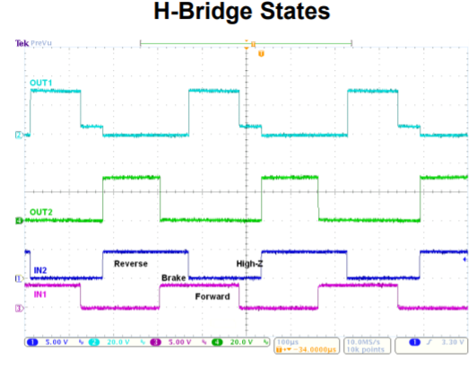
In the datasheet of DRV8872, there is a picture in first page, shown below. Can you help to explain why the OUT1 and OUT2 peform like this in HIGH-Z period?

another problem is from customer, for the different motors, IN1/IN2 is 0/0 mode PWM control, it can’t start motor at the low duty, such as 10%. IN1/IN2 is 1/1 mode PWM control, it can start. 

  • Hi Duoduo,

    We will investigate and reply by Tuesday.
  • Hi Duoduo,

    The picture on the first page shows OUT1 switching from high to high-z while the outputs are unloaded. During this time, the output can have some small leakage causing the voltage to be at ~5V. This can be confirmed by placing a 10kOhm to GND on the outputs.

    OUT2 was at 0V when switching to high-z and did not experience the same leakage.


    "another problem is from customer, for the different motors, IN1/IN2 is 0/0 mode PWM control, it can’t start motor at the low duty, such as 10%. IN1/IN2 is 1/1 mode PWM control, it can start. "

    When PWM'ing between 0/0 coast and reverse/forward, there may not be enough current (torque) to start the motor at low duty cycles. When using 1/1 brake, current continues to flow through the motor which can produce enough torque to start the motor.

    Please ask the customer to examine the motor current in both 0/0 and 1/1 modes.