This thread has been locked.

If you have a related question, please click the "Ask a related question" button in the top right corner. The newly created question will be automatically linked to this question.

DRV8323R: DRV8323R

Part Number: DRV8323R

BLDC_DRV_MOTHER_BROAD_V1.pdfHi,

We are using DRV8323RS in 1x PWM mode

We are able to read and write the values on registers through SPI.

Default values are correct according to datasheet.

But when we are changing it into 1x PWM mode by changing the values of registers. Its show fault.

We have set the values as shown below in registers->

Driver Control Register (address = 0x02) ==> 0x0040

Gate Drive HS Register (address = 0x03)==> 0x0388

Gate Drive LS Register (address = 0x04)==> 0x07AA

OCP Control Register (address = 0x05)==> 0x0159

CSA Control Register (address = 0x06)==> 0x0283

Then it shows Fault according to below registers

Fault Status Register 1 (address = 0x00) ==> 0x0500   (Fault +Indicates gate drive fault condition )

Fault Status Register 2 (address = 0x01) ==> 0x0004  (Indicates gate drive fault on the B low-side MOSFET)

And on GHx its giving 24v and on GLx its giving 0v

And I have attached schematic also, please review it. 

Connections-:

We have connected MCU with EVM according to 1x PWM Mode


Enable pin ==> MCU GPIO (Write High)

SCLK pin ==> SPI Serial clock pin

SDI pin ==> MOSI

SDO pin ==>MISO

nSCS pin ==>Chip Select

INLC (Brake)  ==>MCU GPIO (Write High)

INHC (DIR)  ==>MCU GPIO (Write HIGH)

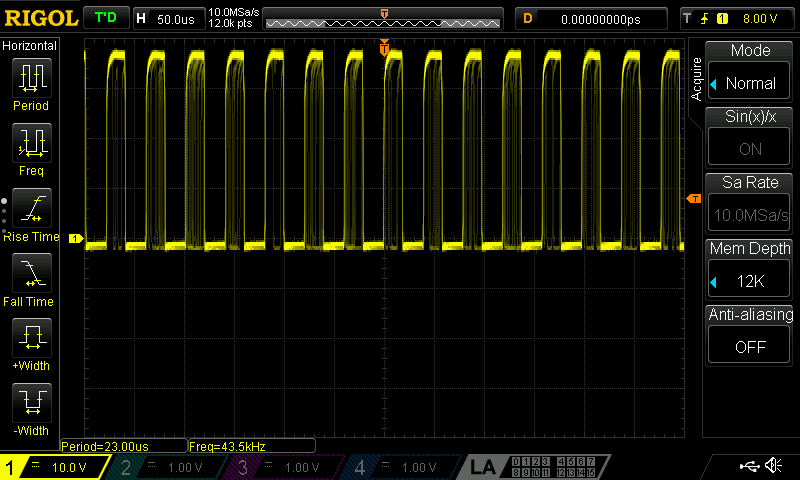
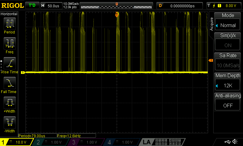
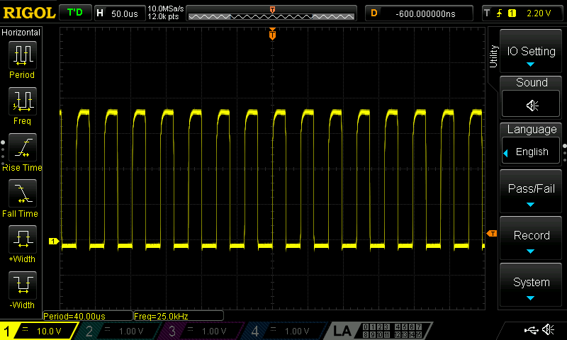
INLA  ==>HALLA of motor

INHB ==>HALLB of motor

INLB ==>HALLC of motor

nFault ==> MCU GPIO (Read High) No fault case

Cal ==> MCU GPIO (Write LOW)

Power Supply 24v

Please help to solve this issue. Thanks in advance.

  • Imran,

    If you are having a LS gate drive fault please check all three phases LS VGS to see if there are any unexpected voltage spikes or transients especially when the LS is supposed to be OFF. Also please check the DRV GND differentially with the FET LS source pins for all three phases.

    Likely you will see there is GND bounce between the system GND (DRV GND) and the FET LS source pins which is causing potential gate drive faults.

    The IDRIVE settings you are using are quite HIGH, this can contribute to gate drive faults. What is the model number of the FET you are using?

    Also can you send a schematic showing component values? It is important to check that for example the caps are the correct voltage rating and capacitance value.

    Regards,

    -Adam
  • Hi Adam,

    Our board got short circuited, So we will get new PCB in few days, then we will able to check the as you said in your initial points.

    Till then I am attaching components values and ratings. Please check it.

    And on nFault pin we were getting LOW (By mistake I had written HIGH).

    And We were giving 42 kHZ with 50% duty Cycle on PWM Pin (INHA).BOMV3.xlsx

    Regards 

    Imran

  • And we are using CSD19534Q5AT MOSFET
  • Imran,

    I cannot reconstruct the Schematic and BOM manually, can you annotate the schematic to show the correct values?

    The FET you are using has a very very small QGD, I would use the lowest IDRIVE setting possible. Using the high setting that you have now will cause issues like gate drive fault and ringing on the GHx/GLx/SHx nodes.

    Regards,

    -Adam
  • Hi Adam,

    I am attaching Schematic with components value.

    BLDC_Power_Card (1).pdf 

  • TAJB225K035RNJ => 2.2 uf
  • Hi Adam,
    Can you please verify the schematic which I had sent you.
    Thank You
  • Imran,

    I see no issue with your schematic, once you have another board please use the lowest IDRIVE setting and check the SHx/GHx/GLx nodes with your scope.

    Regards,

    -Adam
  • Hi Adam,
    We have tried on our new board.
    when I am set the values for 1x PWM. Motor gets jammed. And it seems that motor is trying to rotate.
    As you said I have set the lowest IDRIVE value.
    I have set the values as shown below
    Driver Control Register (address = 0x02)=0x0040
    Gate Drive HS Register (address = 0x03)=0x0300
    Gate Drive LS Register (address = 0x04)=0x0700
    OCP Control Register (address = 0x05)= default value (not changed)
    CSA Control Register (DRV8323x Only) (address = 0x06)=default value (not changed)

    Fault Status Register 1 (address = 0x00)=0x00
    Fault Status Register 2 (address = 0x01)=0x00

    PINS:-
    PWM (INHA)=28 KHz, 50% duty cycle
    Brake (INLC)= Set High
    Dir(INHC)= LOW
    Cal=Low
    And its showing no fault.
    what should I do? Please help me.
  • Please check the switch nodes and gate signals with a scope. Is the fault pin High?
  • Hi Adam,

    Gate_Trigger_High_A

    Gate_Trigger_High_B

    Gate_Trigger_High_C

    Gate_Trigger_Low_A

    Gate_Trigger_Low_B

    Gate_Trigger_Low_C

    Phase_A_OUT 

    Phase_B_OUT 

    Phase_C_OUT 

    And fault pin is High.

    Motor's Phase A and Phase B wire is getting heat up and even motor is also getting heat up.

    Regards,

    Imran

  • Hi Adam,
    Today we tried with same configuration. And motor started rotating.
    But the problem was when ever we were starting the motor we needed to slide rotate the motor by hand and then it use to start rotating.
    And we monitored one more thing, HAL sensor A and B was giving HIGH and LOW signal but, C was continuously LOW.
    For Testing our motor we removed the connections and we found All sensor were working normally. But when we again made the connection, then again motor is not rotating. And nFault pin is LOW. And GLx are low and GHx are high (aprox 5v). And also all Phase A, B, C are high (aprox 5v).

    Regards
    Imran
  • And both Fault status registers are showing no Fault.
  • Hi Adam,

    At the end of the day we found there is issue with brake pin. But even after correcting that issue motor is not rotating.

    and this time we are getting these signals from scope:-

    Phase A output-

    Phase B and C output-

    GHA-

    GLA-

    GHB and GHC-

    GLB and GLC-

    And Motor is getting locked and getting heat up and Phase A wire is also getting heated. A nFault Pin is LOW but Fault status registers are showing no fault.

    Regards

    Imran 

  • Imran,

    Unfortunately it is difficult to resolve this issue remotely. It seems to me that your system is working intermittently. Have you double checked that all phase wires match the phase of the hall inputs? This could explain why sometimes the system is able to work. 

    Regards,

    -Adam

  • To explain more, you need to check that the correlated phase is connected with the same hall sensor. If the hall sensor does not match the phase then you will get intermittent operation.