This thread has been locked.

If you have a related question, please click the "Ask a related question" button in the top right corner. The newly created question will be automatically linked to this question.

DRV8303: DRV8308 BURNED and i don't understend

Part Number: DRV8303
Other Parts Discussed in Thread: DRV8308, SN74CBT3244

HELLO the problem is my DRV burned after a fews minutes.

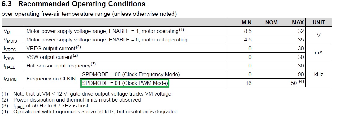
The VM pin have 9 V (the minimum in data sheet is 8.5V ) this is because i need to communicate with them over SPI to read and write the register.
i check everything on my board and no have short circuit is a custom board.

I do this test when I do not have the DRV8308 chip soldered on the board my current in power suply  is 0.01A  or 0.00A 
when i soldered the chip on board is ok with the power suply i put 3.3v on enable pin in DRV8308 and after maybe 5 or 6 minute they burn ...

the output from chip don't use and the Vreg i don't use, in this moment i want communicate over SPI without burned the chip.

I have the Vreg = 5V and Vint =1.79V before they burn.

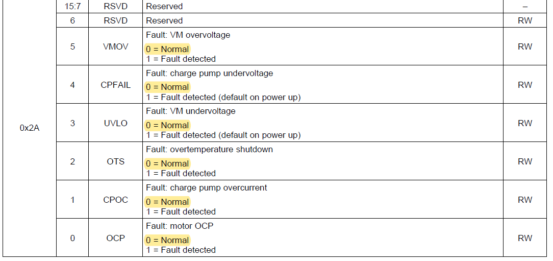
is possible i wrote bad registor on chip?? like turn ON two output in same precise time and they burn?

SR  this is for you https://e2e.ti.com/support/motor-drivers/f/38/p/795516/2964221#2964221


  • Esmith,

    Please send me the complete schematic for review.

    Regards,

    -Adam
  • At this moment this is the circuit each output / input has a jumper in the circuit that allows me to tinnit to make connection.

    At this point the circuit is the same as shown in the figure but I un-solved a DRV8308 chip from the board and found that the lower one was not soldered to the GND large pad.

    What I think is the problem is that the GND pin is not enough to control the whole chip and it is even necessary that the pad under the chip is even soldered to the board.
  • Esmith,

    This ground pad connection is vital to the chip operation. It must be soldered well. This is likely your issue.

    Are you providing only VM power into the device?

    Regards,

    -Adam
  • yes Adam
    i only put 9V to pin VM because is the minimum and with this voltage they burn when i put 3.3V in enable pin...
    Do I need to solder the Isens resistor so it does not burn?

    Although not having the transistor soldered on the board?
    thanks
  • Esmith,

    Yes please populate the sense resistor and FETs as well as the GND pad of the DRV and try again.

    Regards,

    -Adam
  • Hello Adam Sidelsky
    finally i can communicate with the DRV8308 the response from the registor
    and the registor 2A i have 0x18 like the data sheet.

    To read thath i put 9V and welded the final mosfet to drive the motor.

    If i enable the pin ENABLE with 3.3V i have:
    Vreg=5V
    Vint=1.78V

    and i have my led red ON, in my board, this is the FGout active with the default resgistor:
    0x00 = 0000
    0x01 = 0000
    0x02 = 0000
    0x03 = 0000
    0x04 = 0000
    0x05 = 0000
    0x06 = 0000
    0x07 = 0000
    0x08 = 0000
    0x09 = 0000
    0x0A = 0000
    0x0B = 0000
    0x2A = 0018

    IF i write the default resistor and put 3.3V on pin ENABLE the motor don't RUN
    So now i whant to turn ON the motor:
    I want to turn the motor clockwise and anticlockwise. How do I do that?

    SPISettings settings(1000000, MSBFIRST, mode);
    void setup()
    {
    SPI.begin();
    SPI.beginTransaction(settings);
    }
  • Esmith,

    Please check the device datasheet. There are three control modes: Clock Frequency mode, Clock duty cycle mode, and internal register mode.

    Which of these methods do you plan to use?

    Regards,

    -Adam
  • i pretend use a input pwm on pin CLKIN of DRV8308 

    my PWM come from a microcontroler STM32F103xx  at this moment with 19 KHz .
    in the register 0x00 on SPDMODE i pwrite 00bynary

    the response from adress 0x00 is  this 16 bit 0000010100000001 or in hexadecimal 0x0501


     i put:

    pin ENABLE= 3.3V

    pin DIR= 0V
    pin CLKIN = 19 KHz

  • HI Adam

    Where i can found the general STEPS to put the motor spning with sensor or without sensor?

    what i need to do?

    I don't have the VMboard is a custom board.

    The default registor don't do nathing when i put enable =3.3V and DIR=3.3V
  • Esmith,

    I am not sure the issue on your board. Did you check if the fault register is showing any fault? It is stored in 0x2A.

    Can you try the EVM? They are available here: www.ti.com/.../DRV8308EVM

    Regards,

    -Adam
  • HI adam so i search and i find the SN74CBT3244 it's in short circuit i replace it so:

    First step unplug the power supply from my board.

    turn on the power supply and in VM pin on DRV8308 =12v

    i CAN READ THE SPI resgister and write them no problem at this moment :)
    all registor is 0x0000 except the 2A registor i have 0x0018 (this is normal ?)


    so the second  step:

    i increase the voltage on power supply to 25V 
    and i have 24.7V in VM pin on DRV8308 
    i read all resgistor and have the same value 
    all registor is 0x0000 except the 2A registor i have 0x0018 (this is normal ?)

    thirt STEP

    i write this configuration to DRV 8308

           Write in thisRegister HEX = 0x00

           escreveu thisValue hex = 511

           escreveu thisValue bin = 10100010001

    ------------------------------------------------ 

           Write in thisRegister HEX = 0x01    

           escreveu thisValue hex = 0

           escreveu thisValue bin = 0

    ------------------------------------------------      

           Write in thisRegister HEX = 0x02

           escreveu thisValue hex = 4FF

           escreveu thisValue bin = 10011111111

    ------------------------------------------------ 

           Write in thisRegister HEX = 0x03

           escreveu thisValue hex = F82

           escreveu thisValue bin = 111110000010

    ------------------------------------------------ 

           Write in thisRegister HEX = 0x04

           escreveu thisValue hex = 40D2

           escreveu thisValue bin = 100000011010010

    ------------------------------------------------ 

           Write in thisRegister HEX = 0x05

           escreveu thisValue hex = 0

           escreveu thisValue bin = 0

    ------------------------------------------------ 

           Write in thisRegister HEX = 0x06

           escreveu thisValue hex = 0

           escreveu thisValue bin = 0

    ------------------------------------------------ 

           Write in thisRegister HEX = 0x07

           escreveu thisValue hex = 0

           escreveu thisValue bin = 0

    ------------------------------------------------ 

           Write in thisRegister HEX = 0x08

           escreveu thisValue hex = 0

           escreveu thisValue bin = 0

    ------------------------------------------------ 

           Write in thisRegister HEX = 0x09

           escreveu thisValue hex = 0

           escreveu thisValue bin = 0

    ------------------------------------------------ 

           Write in thisRegister HEX = 0x0A      

           escreveu thisValue hex = F000

           escreveu thisValue bin = 1111000000000000

    ------------------------------------------------ 

           Write in thisRegister HEX = 0x0B

           escreveu thisValue hex = 0

           escreveu thisValue bin = 0

    ------------------------------------------------ 

           Write in thisRegister HEX = 0x2A

           escreveu thisValue hex = 0

           escreveu thisValue bin = 0

    ------------------------------------------------


    AND READ THIS VALUES 


    Read Register: 0x00

    bits do CTRL_DRV8308 BIN -> contem 10100010001

    bits do CTRL_DRV8308 HEX ->511


    Read Register: 0x01

    bits do Adress_ADVANCE BIN ->0

    bits do Adress_ADVANCE HEX ->0


    Read Register: 0x02

    bits do Adress_COMCTRL BIN ->10011111111

    bits do Adress_COMCTRL HEX ->4FF


    Read Register: 0x03

    bits do Adress_MOD120 BIN ->111110000010

    bits do Adress_MOD120 HEX ->F82


    Read Register: 0x04

    bits do Adress_DRIVE BIN ->100000011010010

    bits do Adress_DRIVE HEX ->40D2


    Read Register: 0x05

    bits do Adress_SPDGAIN BIN ->0

    bits do Adress_SPDGAIN HEX ->0


    Read Register: 0x06

    bits do Adress_FILK1 BIN ->0

    bits do Adress_FILK1 HEX ->0


    Read Register: 0x07

    bits do Adress_FILK2 BIN ->0

    bits do Adress_FILK2 HEX ->0


    Read Register: 0x08

    bits do Adress_COMPK1 BIN ->0

    bits do Adress_COMPK1 HEX ->0


    Read Register: 0x09

    bits do Adress_COMPK2 BIN ->0

    bits do Adress_COMPK2 HEX ->0


    Read Register: 0x0A

    bits do Adress_LOOPGAIN BIN ->1111000000000000

    bits do Adress_LOOPGAIN HEX ->F000


    Read Register: 0x0B

    bits do Adress_SPEED BIN ->0

    bits do Adress_SPEED HEX ->0


    Read Register: 0x2A

    bits do Adress_FAULT BIN ->10000

    bits do Adress_FAULT HEX ->10

    escrita no registo RSVD VMOV CPFAIL UVLO OTS CPOC OCP
    0X0018 0 0 0 0 0 0 0 0 0 0 0 1 1 0 0 0
    0X0010 0 0 0 0 0 0 0 0 0 0 0 1 0 0 0 0


    CPFAIL IS ? [->Fault: charge pump undervoltage<-]  information from data sheet pag 40.

    when i measure i have:

    VCP = 24.03 V

    VM=24.76 V 
     
    I have the same capacitor like the EVMboard and datasheet say.

    when i try to run the motor they don't run  BEACAUSE the erro 0x0010 i think.

    i try run put the PWM  19KHz signal in CLKIN  and ENABLE =3.3 V  and DIR pin=3.3 V 


    so how i fix the error? how bits i need to change??
    the Vreg, suply my motor hall sensors, MOTOR IS  BLDC Motor 57HBL03/ DC24V / 4000rpm / 0.43 NM 


  • ADAM  i do some test and this is the result

    and  i have this values after i write in the registers, and put ENABLE pin=3.3V
    Read Register: 0x2A

    bits do Adress_FAULT BIN ->10000

    bits do Adress_FAULT HEX ->10

    I see the VCPUMP  and i confirme the voltage on VCP pin is have more 10V the VM pin when the enable pin is active

    in the registor 0x00 i have the bit 0 in ENPOL 

    I DO :

    ENABLE pin =3.3V
    VM=24V 

    VCP= 34V

    AND WHEN 
    ENABLE pin=0V

    VM=24V

    VCP=24V

    wath is the metod to read the resistor on SPI?

    i need to enable pin to have the Vreg and Vint? 


  • Esmith,

    Yes the enable pin needs to be high so that the charge pump, VREG, and SPI will operate.

    Regards,

    -Adam
  • HI Adam,

    I CHECK everitihng i now, but not work....

    i change the motor and I have an additional 10 V on VCP over VM.
    this happens when i have 3.3V on enable PIN.

    when i read the registersr i put the ENABLE pin =3.3V so the VCP pin have more 10 V over VM pin. IT work when i read the register 0x2A

    so for me it work fine for the condition to work the motor i have VM=24v 
    vcp=34V , Vreg=5V, Vint=1.8V, ENABLE pin=3.3V and DIR pin = 3.3V 

    the PWM =19KHz with 60% duty cycle. 
     so i need a star to solve my problem... any ADVICE? to help me?


    i have error 0x51

    read from Acess Register: 0x2A

    bits do Adress_FAULT BIN ->1010001
    bits do Adress_FAULT HEX ->51

    I don't UNDERSTEND why i have a CPFAIL if the voltage change to more 10V over the VM voltage

    I have the led FAULTn ON / alight when i have ENABLE =3.3 V if ENABLE=0 V i don't have the FAULTn ON.  

  • Esmith,

    Did you try clearing the faults once your system is fully powered and stable?

    Regards,

    -Adam
  • Hello Adam,

    yes i clean but when i read they give the error.

    to clean the register 2A  i write this values 

    #define BLDCDRV_REGVAL_0X2A 0b0000000000000000 /**< FAULT 0x0000*/

    write everything with zero .

    after i read and have 0x0010 or 0x0011 or 0x0019 or 0x0050 or 0x0051 or 0x0059

    my motor don't RUN but  turn only 90ºdegree or 270º degree...or the engine vibrates

    the idea is when i put 3.3V in pin ENABLE the motor RUN 

    thanks


  • Esmith,

    It is likely that you have the wrong hall sensors connected to the wrong phases. Please check that phase U of the motor connection to the DRV matches phase U hall input to the DRV. Do this for W and V as well.

    If you have the W hall connected where the V hall should be, for example, the motor will behave as you mentioned.

    Regards,

    -Adam
  • Hello ADAM,

    my motor RUN finally but i don't understand WY i have a Fault...

     
    read Acess Register: 0x2A

    bits  Adress_FAULT BIN ->10000
    bits  Adress_FAULT HEX ->10


    0x2A register RSVD VMOV CPFAIL UVLO OTS CPOC OCP
      0X0000 to reset 0 0 0 0 0 0 0 0 0 0 0 0 0 0 0 0
      0X0018 (normal fine) 0 0 0 0 0 0 0 0 0 0 0 1 1 0 0 0
       0x0010  motor RUNNIG  0 0 0 0 0 0 0 0 0 0 1 0 0 0 0

    ERROR CPFAIL =>1 = Fault detected (default on power up)

    HOW  i remove the error ? when the motor running i write in register 0x2A all zeros 0x0000. don't solve the problem.
    when i write zeros when the motor is STOP do not solve the problem.

    what i need to do ADAM ??  to solve this problems???

    The motor start RUNNING when i change the register 0x04.

    best regards Adam

  • Esmith,

    The system is indicating that you have a VM and/or CP voltage issue. Have you monitored the VM and CP supplies throughout the whole startup/motor spinning process?

    What did you change in register 0x04 to make the motor spin?

    Regards,

    -Adam

  • that is my definition for the registor i write the 16bit  0b say to the microcontroller thath number is binary 

    #define BLDCDRV_REGVAL_0X00 0b0100000001010000    /**< CTLR 0x4050*/ 
    #define BLDCDRV_REGVAL_0X01 0b0000000000000000    /**< ADVANCE 0x0000*/
    #define BLDCDRV_REGVAL_0X02 0b0000010011111111      /**< COMCTRL 0x04FF*/ 
    #define BLDCDRV_REGVAL_0X03 0b0000111110000010     /**< MOD120 0x0F82 */ 
    #define BLDCDRV_REGVAL_0X04 0b0110010111111111      /**< DRIVE 0x65FF*/ // it running ensine is 120º
    #define BLDCDRV_REGVAL_0X05 0b0000000000000000    /**< SPDGAIN 0x0000 */
    #define BLDCDRV_REGVAL_0X06 0b0000000000000000    /**< FILK1 0x0000*/
    #define BLDCDRV_REGVAL_0X07 0b0000000000000000    /**< FILK2 0x0000*/
    #define BLDCDRV_REGVAL_0X08 0b0000000000000000    /**< COMPK1 0x0000*/
    #define BLDCDRV_REGVAL_0X09 0b0000000000000000    /**< COMPK2 0x0000*/
    #define BLDCDRV_REGVAL_0X0A 0b1111000000000000     /**< LOOPGN 0xF000*/
    #define BLDCDRV_REGVAL_0X0B 0b0000000000000000    /**< SPEED 0x0000*/
    #define BLDCDRV_REGVAL_0X2A 0b0000000000000000    /**< FAULT 0x0000*/
    in the registor 0x04 i change the times to the maximum #define BLDCDRV_REGVAL_0X04 0b0110010111111111 /**< DRIVE 0x65FF*/ // it running ensine is 120º
    so the motor is running but i change the bits IDRIVE to 111 [130mA]    DTIME to 111[1,5uS]    TDRIVE to 11 [15uS]  this way the motor run.


    when i change TDRIVE to 01 [5uS] they burn my external FET IPB090N06N3 G 
    Now i change all FET and they run in vibration mode and burn the fet number 3 and 1.

    yes i have the VM=24V and VCP=24V when enable is HIGH my VCP change to 34V 
    and in the scope i have a delay between the time enable pin high and VCP change 24V to 34V is 520uS (microsenconds) 

    When i gonna read from SPI i put enable  wait 2second to have time the VCP  "wake up/change values" and the register 0x2A say 10000 is VCPFAIL active 
    my capacitor on the board is the same from the PDF on demo board  
  • Adam 

    is normal have one FET always ON? when no motor connected?  no sensor?

    in my board now my engine wheel but bumps/vibrate ...  

    Do you have more test for i see if my DRV is GOOD? OR NOT?

    I can communicate change the registor vm=24v the VCP  change the 24V to 34V  i have Vreg=4.8V and Vint =1.8V 

     i have WHSG is HIGH that polarize my transistor in phase W

  • Esmith,

    No, one FET should not always be on, likely your DRV is damaged.

    If your FET is getting damaged with lower TDRIVE then I would suggest checking the gate waveform, probably you will see anomalies on the gate signals. When checking the gate signals always check it differentially from Gate to Source.

    No I do not have an absolute way to check if your DRV is good or bad.

    Regards,

    -Adam

  • Adam,

    my motor as work with CPFAIL active afeter 2 hours working the motor not RUN again...

    this moment  

    Acess Registor: 0x2A

    bits do Adress_FAULT BIN ->10000
    bits do Adress_FAULT HEX ->10

    that say i have a fault detected (default on power up) what this mean??

    We have two moment to say power up...
    first  moment         is when we plug the 24V battery/ power supply???
    second moment    is when we put enable pin HIGH?

    what is happening now is that you can make a 24V supply to reset the DRV8308.
    I read the records all with 0x0000 and 0x2A with 0x0018.
    I try to run the engine and it does not work.

    I write my records
    and I certify that he writes when he reads and he is writing.

    I turn on the engine it spins type one second and then stops,
    I still can not get the CPFAIL error.

  • Esmith,

    After the engine spins for 1 second and stops, is the fault pin low? What do you see on register 0x2A after the engine spins and stops?

    It is normal to see 0x2A as 0x18 at startup (once the VM rises above the VM reset threshold). Register 0x2A must be reset by writing 0x0000 after VM rises above the VM reset threshold.

    Regards,

    -Adam

  • hello Adam,

    " once the VM rises above the VM reset threshold "

    where i can find the value on data sheet for VM reset? 

    I need change my power FET because they have more than 20V on Vgs .... this value is if i use a power suply with 24V

    (so it burned the Fets and the DRV with reverse voltage, burned the DRV, also put a resistance of 33ohms in the gate of the fets.)


    now i have other PROBLEM, if i shutdown all system.

    In the next day when I turn on the engine I need to help turn the motor shaft to turn.

    Then it swings back and forth smoothly.

    THE ACTUAL register

    #define BLDCDRV_REGVAL_0X00 0b0100000001010000 /**< CTLR 0x4050*/
    #define BLDCDRV_REGVAL_0X01 0b0000000000000000 /**< ADVANCE 0x0000*/
    #define BLDCDRV_REGVAL_0X02 0b0000010011111111 /**< COMCTRL 0x04FF*/
    #define BLDCDRV_REGVAL_0X03 0b0000111110000010 /**< MOD120 0x0F82 */ 
    #define BLDCDRV_REGVAL_0X04 0b0101100011111111 /**< DRIVE 0x58FF*/
    #define BLDCDRV_REGVAL_0X05 0b0000000000000000 /**< SPDGAIN 0x0000 */
    #define BLDCDRV_REGVAL_0X06 0b0000000000000000 /**< FILK1 0x0000*/
    #define BLDCDRV_REGVAL_0X07 0b0000000000000000 /**< FILK2 0x0000*/
    #define BLDCDRV_REGVAL_0X08 0b0000000000000000 /**< COMPK1 0x0000*/
    #define BLDCDRV_REGVAL_0X09 0b0000000000000000 /**< COMPK2 0x0000*/
    #define BLDCDRV_REGVAL_0X0A 0b1111000000000000 /**< LOOPGN 0xF000*/
    #define BLDCDRV_REGVAL_0X0B 0b0000000000000000 /**< SPEED 0x0000*/
    #define BLDCDRV_REGVAL_0X2A 0b0000000000000000 /**< FAULT 0x0000*/
    on page 20 of data sheet in register 0x03 to put the motor with 120º i need to write 3970 decimal converting to binary (0000 1111 1000 0010)?