This thread has been locked.

If you have a related question, please click the "Ask a related question" button in the top right corner. The newly created question will be automatically linked to this question.

DRV8302: Output 6 PWM problem

Part Number: DRV8302

Hello.

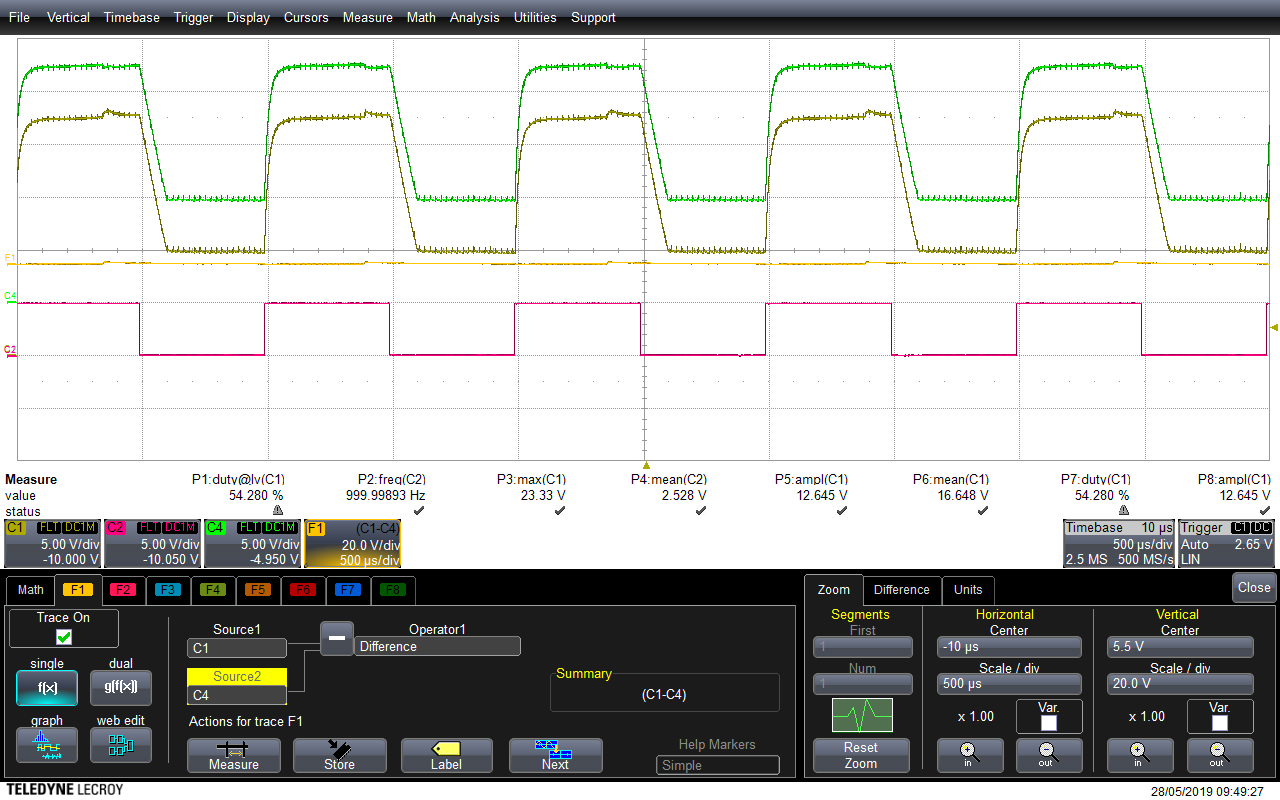
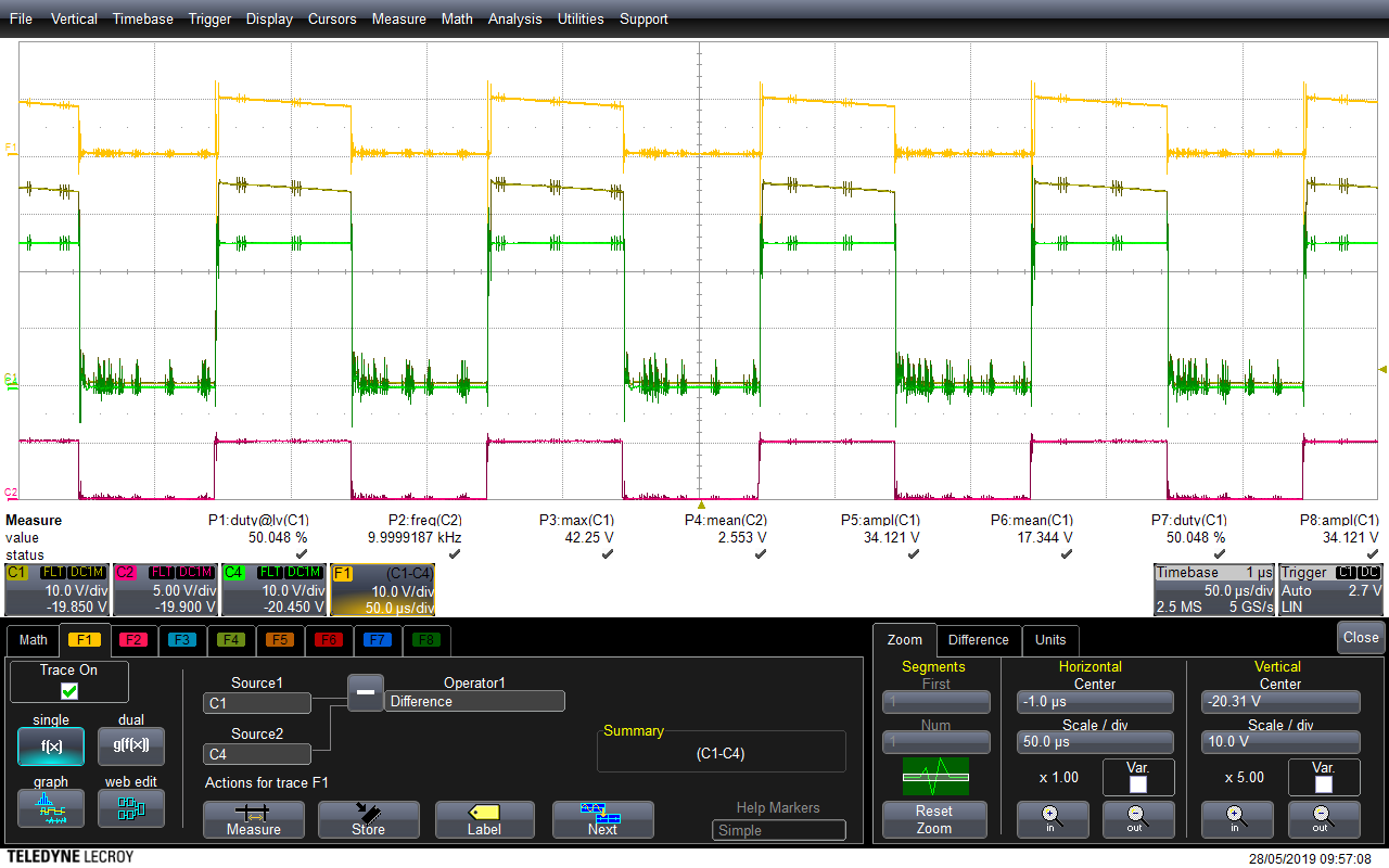
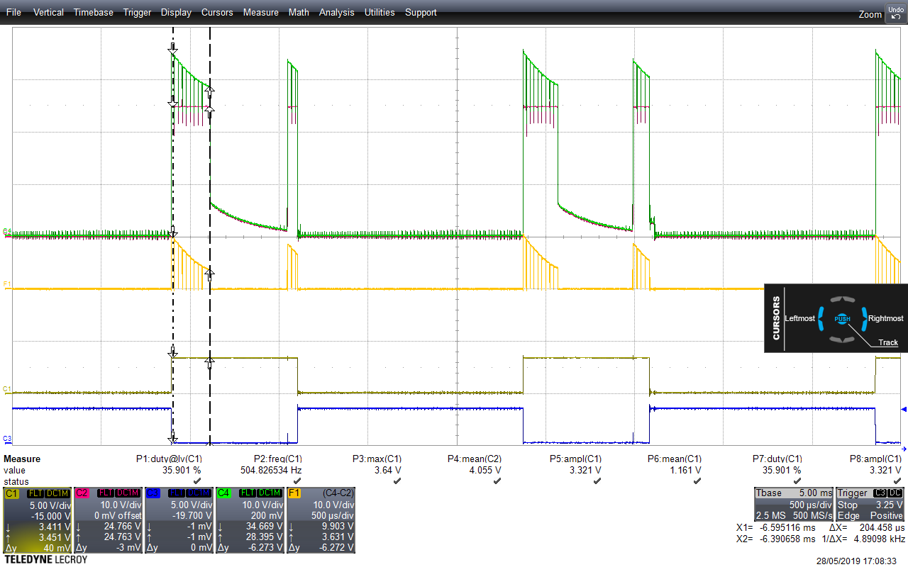
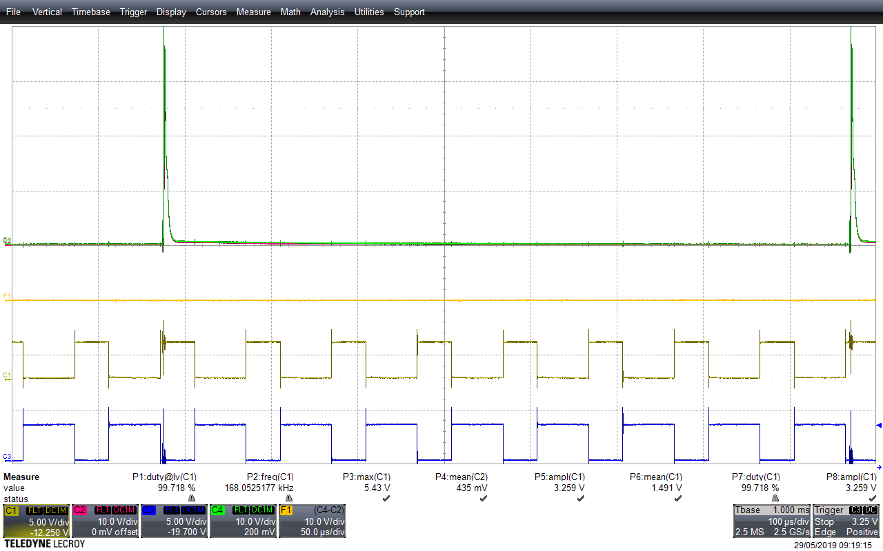
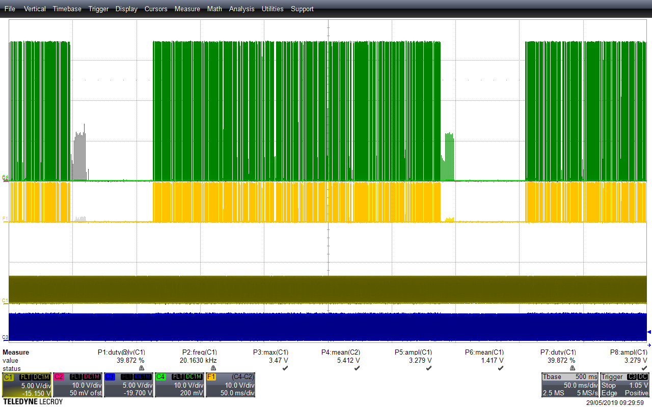
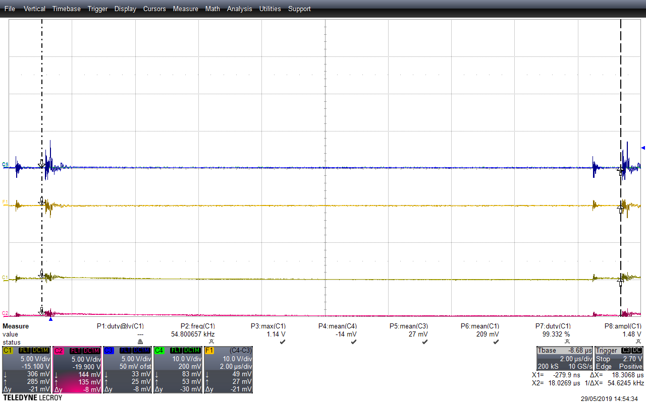
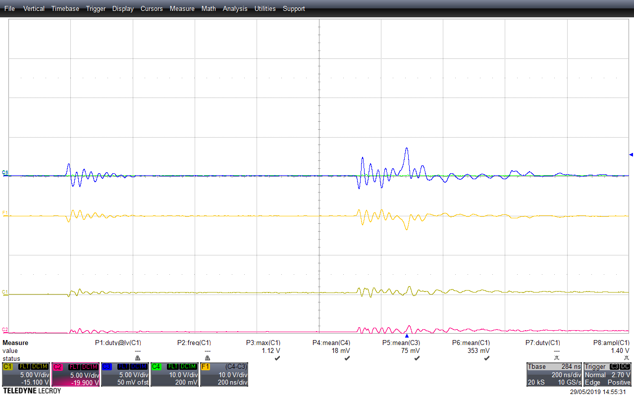
I wish to use the DRV8302 to drive a brushless motor. During my unitary test of said driver I saw that the output is not as expected when using the 6-PWM mode. On the image hereunder I have nFAULT and nOCTW on C1 and C2. C4 is my input onto INH_A which is coming from a function generator. C3 is the ouput I get on GH_A.

The signal is measured in regard to the common ground.

This problem is not observed on the low side nor when using a 3-PWM mode (high and low side).

Do you have any explanation ?

Thank you.

  • Thibaut,

    The high side FET is not referenced to GND, it is floating on the motor switch node. Please check the same measurement using a differential probe between the high side gate and high side source connection.

    How are you driving 6x PWM with the function generator?

    Regards,

    -Adam
  • Adam,

    Thanks for your fast response.

    To put a bit more of context on the test I am doing the test without the FET connected and deactivated the protections to avoid output cut-offs. As you asked I did the same measurements using a differential probe. The probe used is a Lecroy ZD1500.

    Regarding your second question, I generated the 6x PWMs using a microcontroller (STM32F4) to make both original and complementary signals but since the results were not as expected I went back to use only one input (using function generator) in 6xPWMs mode and monitoring only one output.

    Best.

  • Hi,
    Sorry forgot to say that C4 is the input and C3 is the output. C2 is not really used and C1 is nFAULT.
  • Thibaut,

    You should connect the FETs and a motor, then check for the expected output.

    Regards,

    -Adam
  • Adam,

    Since the output signals are not as expected I would prefer to avoid making any more connections that could damage the driver, the fets or the motor.

    Do you have any other idea as to where the problem could come from or another way of testing without the FETs and motor ?

    Cheers.

  • Thibaut,

    The DRV is designed to work with a FET including it's inductance, capacitance, etc. Without this FET, the driver cannot operate correctly since it cannot correctly maintain things such as Vgs monitoring, Vds monitoring, Slew rate control, etc. The device protection modes should prevent the device/FET/motor from being damaged.

    If you need a reference for a working system, please order an EVM.

    Regards,

    -Adam
  • Adam,

    Following your advice I connected the FETs to the output of the driver and the results were still the same. Any suggestions ?

    Cheers.

    UPDATE :

    With the FETs connected I did a new check of my voltages on SH_X, GH_X. When in 6-PWMs mode I see as follows (C1 is GL_X, C2 is INH_X, C4 is Sh_X and F1 is C1-C4) :

    Then I did the same measurement in 3-PWMs mode. The results are as follows :

    As you can see in 6-PWMs I dont have the ~11V needed to turn on the FET. The problem should thus be regarding the GVDD but checking it did not show anything.

  • Thibaut,

    What are you seeing on GVDD? The Vgs in 6x mode shows no voltage!

    Regards,

    -Adam
  • Adam,

    GVDD is stable at ~11V.

    Here is something interesting :

    In pink (C2)  I have SH_1, in green (C4) GL_1 , C1 and C3 are respectively INH_1 and INL_1 in 6-PWM mode however this time I also applied 5V onto INL_3. The FET stage is completely wired and the motor is "simulated" using 500ohm resistors. Any ideas ?

    Cheers.

    EDIT :

    I changed the PWM frequency from the 500Hz to 10kHz and 20kHz and it works better (same as in 3-PWM mode). However I often get as follows :

    Observing nFault at the same time shows that it goes to 0V from time to time. I think it may come from the noise that is everywhere, power supply included. Any other ideas ?

    EDIT 2 :

    The "noise" is weird, it's always the same and it's periodic, like so : 

    Also, this "noise" only appears when a Voltage different than 0 is applied to any of the gate input (INH_X or INL_X).

    EDIT 3 :

    I can't post the figure right now and will have to wait for monday but the noise came from faulty probes. That's one point. The other one with the cutoff is clearly coming from nFault. Observing GVDD more closely I do have undervoltages happening but they do not seem to all trigger nFAULT. I have GVDD going from 7.5V to 14V. It is not said in the datasheet how much time does GVDD has to be in undervoltage to trigger the fault. This happens relatively often for PVDD > 32V and PVDD < 28V but around ~30V it is less often. 

    I tried to put a bigger capacitor on GVDD pin but it did not seem to do much. Any suggestions ?

  • Thibaut,

    Thanks for the information. Under what condition to you have GVDD dipping down to 7.5V?

    Regards,

    -Adam
  • Adam,

    Under "normal"conditions, the drop in voltage does not happen on a fixed period but randomly.
    I apply a 20kHz PWM at 35% duty cycle onto INH_A, the complementary PWM (65% 20kHz) onto INL_A and 5V constant onto INL_C. The resistance on the gate lines are 4.7ohm. I also added a zener diode (17V) and resistance between the gate and source of each FETs for protection.

    Cheers,
  • Thibaut,

    You mentioned that you are not using a motor. Can you try the same experiment with an actual motor? Also can you show an image of the setup and a schematic of your resistor load?

    Regards,

    -Adam
  • Adam,

    Here is the image of the setup, it is quite rudimentary. Usually the stm32 board  connects to the INH_A and INL_A and a 5V cable goes to INL_C . There is a 5V line on top of the stripboard and GND at the bottom. The GND from the power pad is connected to the other ground and the stm32 ground is also connected to the rest.

    The resistor charge between phase a/b and b/c is 500ohms which leaves a 1kohm between phase a/c.

    Cheers,

    EDIT :

    Reconnected everything, the GVDD seems to hold now even though no changing were made however nFAuLt latches regularly when the power stage is powered. when only connected (fets connected tout drv) there is no problem but when current is going through it latches even though I connected OCADJ to 3.3V

  • Thibaut,

    Can you try this with an actual motor? Do you have access to an EVM?


    Regards,

    -Adam