This thread has been locked.

If you have a related question, please click the "Ask a related question" button in the top right corner. The newly created question will be automatically linked to this question.

DRV8873SEVM: Charge-pump undervoltage

Part Number: DRV8873SEVM
Other Parts Discussed in Thread: DRV8873

Hello there,

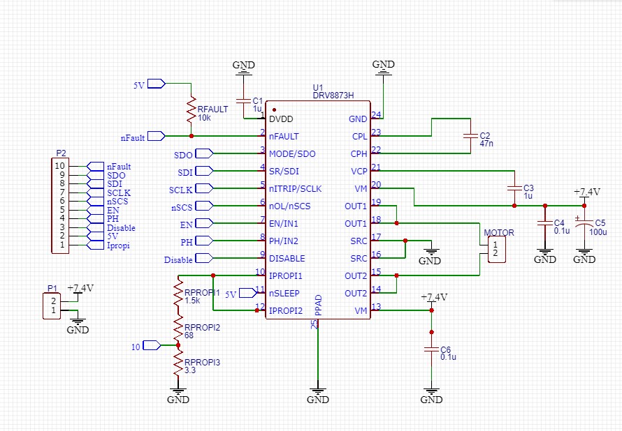
I am new in the motor driver industry. I made a breakout board by my self for the DRV8873S DC motor driver. I guess the schematics, breakout board and the components are all correct, according to the datasheet. It keeps sending me CPUV fault condition via SPI and i don't know how to get this thing working. The VM voltage is 7.4V. 

Thanks in advance!
Best regrads, Nikita

  • One thing to add, i use 3.3 kOhm Rfault resistor instead of 10 kOhm and 5V pin on my MC for pull-up

  • Hi Nikita,

    The schematic and layout appear to be correct.

    Have you looked for a short on the board between the CPH and VCP pin, or VCP and VM?

    Have you measured the CP voltage when the device is active and the charge pump should be up?

    If not please do, and report the voltage. 

  • Thank you for your reply!

    Visually there are no shorts between pins you mentioned. Two days ago, when i first tested the driver and got CPUV condition via SPI i measured the voltage of VM = 7.4V and VCP= 11.4V (VM+5 as it is said in the datasheet). I should mention, that since i had no proper Rfault resistor (10kOhm) i decided not to solder any, because in my first test i had no need of nFAULT pin. After i got a CPUV fault i thought having no Rfault may cause this issue, so i decicded to solder at least 3.3 kOhm. 

    I don't know may information i mentioned above be relative to the problem, but now i measure 7.4V between VM and GND, and the voltage between VCP and GND keeps falling, starting from 6.8V till it reaches 0V.. No stable 11.4V. That is strange.  

    Another strange thing. I had set DIS_CPUV bit to 1, then set CLR_FLT bit to 1, but the CPUV and fault bits haven't gone.

    I use 100 microF bulk capacitor. Maybe it is too big?

  • Hi Nikita,

    The VCP voltage is incorrect as it should be ~VM- 0.7V when the device is in sleep mode, and ~VM+5V when the device is not in sleep mode.

    Do you recall what testing was performed prior to the discovery of the CPUV fault?

    If you have a second board, I suggest trying it.

    When you initially try the second board, set a current limit of 100mA and a voltage of  6V.
    Do not load the outputs
    Confirm the device wakes up properly and the input control the outputs according to the truth table selected.
    Once everything is confirmed operational, the outputs can be loaded and the voltage and current limit can be increased.

    The 100uF bulk capacitor should not be a problem.

  • Hello Rick,

    The very first test was sending digital signal of 5V from microcontroller to IN1 and IN2. I have a 12V PS and a DC-DC converter, which outputs a maximum of 7.4V, 3.2A. Nothing happened, motor did not move and after that i started my investigation and had several tests with SPI and how it works on the driver (never had a close look a SPI before), might i have damaged something sending wrong SPI commands? Right now everything works fine with SPI, bits are changing, commands are sending correctly. 

    Yes, i have 2 more DRV8873 ICs, but it will take quite a long time to create another breakout board.. If there is any chance to check something else using current breakout and driver, it would be great. Can you suggest checking anything else? Can I try setting current limit of 100mA and a voltage of 6 on this board? And should I disconnect the motor from the breakout while testing?

    May it be a hardware problem? Should i try desoldering capacitors between VM and VCP, CHL-CPH and replace with new ones?

    Thank you in advance!

  • Hi Nikita,

    You can try the DRV8873 unloaded with a lower voltage and current limit. Based on the VCP voltage, I am assuming the IC has been damaged.

    It may be difficult to continue the investigation without replacing the IC or creating another breakout board.

  • Hi Rick,

    If it was damaged and we do not know how, it would not be nice to kill another one the same way :D

    So, It would be great to understand, what caused the issue. I will try everything we have talked about today and reply.

    Thank you for support!

    Update:

    Tried everything, the VCP voltage on the trace is still changing from VM Voltage to zero... But on the IC VCP pin it appear to be stable 5.6V in active mode and 5.86V in sleep. Think you are right about the IC.. Will try another one on the same breakout board when the 10 kOhm resister for Rfault.

    Trying to investigate the issue of damaging the IC. I have connected the nSLEEP to the 5V pin of my Arduino Uno microcontroller. As it is said in the datasheet for the MC the 5V pin produces up to 500mA. Before i had pull-uped the nFAULT with this 5V pin and with 3.3 kOhm Rfault resistor i had stable 11.4V on the VCP. Maybe to small resistor caused the issue? How do you think?

  • Hi Nikita,

    The 3.3k resistor on nFAULT is not a problem. I agree it would be nice to understand what caused the issue.

    The problem is I can only guess since I don't know everything that was done to the device. Having said that, here are a few possible causes.

    Allowing the device to absorb moisture prior to soldering the device to the board. If exposed to moisture, the device should be baked to remove the moisture prior to soldering.
    Too much heat when attaching the IC to the board. There is a recommended temperature profile for soldering the device to the board.
    Connecting the power supply in reverse -- probably not that
    Running at a slow slew rate and high current -- there is a note in the datasheet
    Shorting pins/nets when probing

  • Thank you very much!

    I think i am going to order some more ICs for tests)
    About the moisture, i have that piece of paper saying LEVEL 2 PARTS and LEVEL 2A-5A PARTS which was in the package since i had received the ICs. Which level does DRV8873S belong to? 60% percent is blue, 10% and 5% are pink, should i bake it and how?

    Talking about slow slew rate with a high current, datasheet says about 8A current, but i have just 3.5Amps and the 10.8-V/μs rise time.

    What do you mean by saying "Shorting pins/nets when probing"?

    Best regards, Nikita

  • Hi Nikita,

    MSL Level is 3.

    It is possible that you had more than 3.5A depending on the PWM'ing of the motor. If available, please using a current probe to monitor the motor current the next time you connect the motor.

    Scope probes and DMM probes can slip and short across pins or components. This is a problem with probing when powered up, which I have done several times. Usually I know right away when damage occurs.

  • Hi, Rick,

    By the way, which pins should I never short while probbing?

    Best regards, Nikita

  • Hi Nikita,

    The device is designed to protect against the outputs shorted to ground and to VM.

    It is just good practice to be very careful when probing on powered devices. If something goes wrong, it is difficult to identify the cause.

  • Hello Rick,

    I finally got it working! I made everything we had talked about:

    1. Baked the new DRV8873S for 7 hours 125C in electric oven and then soldered it;

    2. Soldered new capacitors and 10 kOhm Rfault;

    3. Set current limit to 350mA, voltage limit to 6V;

    4. VCP voltage is 11V now as it is supposed to be;

    5. Checked the output voltages without load due to the truth tables;

    6. Connected the motor.

    Thank you for the great support! Have a nice day!

    Best regards, Nikita

  • Hi Nikita,

    Glad we could help. Thanks for following up.

    Good luck with your evaluation.

  • Hello Rick,

    Again... Same CPUV fault... The VCP voltage is the same as VM.. But now, during the operation of a motor GND of the DRV8873 breakout somehow disconnected and now i have this issue. May the disconnection damage the IC? I have to disolder the IC again now or I can make something?

    Thanks in advance, Nikita

  • Hi Nikita,

    I will support you now.

    Can you clarify what you mean by disconnected motor GND?

    Do you mean the ground reference to the board?

    What did it disconnect from?

    CPUV permanent fault can be caused when the charge pump is damaged, e.g. from an overvoltage condition on it.