This thread has been locked.

If you have a related question, please click the "Ask a related question" button in the top right corner. The newly created question will be automatically linked to this question.

DRV8872: Unexplained behavior on motor output

Part Number: DRV8872

Hello, 

I am using the DRV8872 motor driver to drive a brushed DC motor. Although the motor driver is driving the motor, I am observing bad signals on the motor output line and want to know what is causing this in case it is indicative of an underlying issue. 

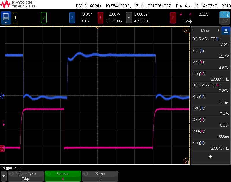
Here is a scope image of what I am seeing. Blue is one of the motor output lines and pink is the corresponding motor input line (It is the same for the other set of input/output). The motor input is being PWM driven at 20kHz frequency and 25% duty cycle. 

If you zoom in, you can see the motor output line exhibits many weird behavior on rising and falling edge. 

Is there any explanation for what is causing the motor output signal to look like this? Or suggestion for improvements to correct the behavior. 

Thank you.

  • Hi Grace,

    Is a load(motor) connected? If yes, have you tried comparing the signals without a load(motor) connected?

    Is the ITRIP threshold reached during those spikes?

  • Hi Hector,

    Yes, the load is connected. It's a brushed DC motor internal to a linear actuator. I believe that without the load the signals look like straight edges. 

    No, I do not believe the ITRIP threshold is reached because I currently am not using an ISENSE resistor (have the pin tied to ground) and the motor stall current is only 2A. 

    Thank you.

  • Hi Grace,

    Can you provide a scope capture of IN1, IN2, OUT1, and OUT2, and another scope capture of IN1, VM, OUT1, and OUT2?

    Is there any discrete components between OUT1 and OUT2 aside from the motor?

    Can you measure the two motor leads for capacitance?

    Do you know if this motor has wear and tear or is it brand new? 

  • Hi Hector, 

    I can update with additional scope captures later. 

    The only other components on the motor output lines besides the motor are TVS diodes. 

    I tried measuring the motor leads for capacitance using a DMM, but the limit on my DMM is 4000uF and it's saying the capacitance is greater than that. I'm not sure if the value makes sense or if I did something wrong when measuring. 

    The motor isn't brand new but is only a few months old. 

    Thank you.

  • Hi Hector, 

    Could you explain how different motors (loads), like capacitance or inductance of motor, affect the performance of the H-bridge? 

    Thank you.

  • Hi Grace,

    Found some good explanations online for you:

    The capacitor seen on a lot of brushed motors is there to absorb RF noise due to the arcing as the brushes commutate. You often see these on the motors used in RC cars, where the motors are fairly powerful and spinning fast.

    The problem comes when you are using PWM to drive the motor. At the beginning of the duty cycle, when the current is switched on, you'll see a current spike as the current rushes into the capacitor from the H-Bridge. This inrush current can sometimes cause noticeable voltage ripple at the power supply, adding noise into any sensitive analogue sensors.

    To prevent the inrush current, you can add a pair of inductors between the H-Bridge and the capacitor. This will hold the current fairly steady. Actually, you'll often see inductors on motor drive circuits anyway. Even though the motor itself is an inductor, it's often quite a low inductance, so extra inductance is added to help smooth out any current fluctuations when using PWM drive.

    While high inductance values may limit the system bandwidth, low inductance values can lead to control loop instabilities, inaccuracies in current readings, increased power losses and other problems.

  • Hi Hector,

    So should I try adding two inductors in series (one between each motor driver output and motor terminal) or one inductor in parallel (one in between both the motor terminals)? 

  • Let us analyze the scope captures first to determine if the behavior is acceptable. If we determine it could be an issue, then corrections can be considered.

    What is the bulk, bypass capacitances on your H-Bridge?

    What is the expected peak current and RMS current the H-Bridge will experience?

  • Hi Hector,

    Due to the setup, it is difficult for me to capture 4 signals on the scope at once. Here is a scope capture of IN1 (pink), OUT2 (blue), and VM (green). 

    And zoomed in image:

    Based upon my opinion, this doesn't look like the voltage is sagging enough to indicate large current spike. 

  • Additionally, here is my schematic for the motor driver output side. 

    The expected peak current is 2A and RMS current should be around 0.8-1A range. 

  • Hi Grace,

    Is there any additional capacitance on V24P0_MOTOR?

    Are you probing V24P0_MOTOR, IN1, and OUT1 as close to the device as possible?

    Can you provide a scope capture of IN1, IN2, and OUT1?

    Is the ambient temperature the system tested on the expected ambient temperature when in operation? If not, how big is the delta and what is the current ambient temperature?

  • Hi Hector, 

    Yes, there is one more 10uF capacitor on V24P0_MOTOR. 

    Yes, I am probing not directly on the leads of the IC, but on breakout testpoints close to the leads. 

    Yes the temperature is what is expected. It's at room temperature. 

    Another thing to note is I have tested an entirely different motor and I do not notice these characteristics with the other motor. In fact the signal looks much better and the edges are smooth. So I'm thinking it has to do with how the original motor is loading the motor driver to cause these weird behaviors so modifications may be necessary. However, I don't know how to characterize the two different motors in order to determine what differing factors between the two motors could be causing this behavior. 

    Thank you.

  • Hi Grace,

    Can you utilize that second motor instead?

    Very good catch.

    Now, different motors mean different build materials, brush metal quality, wear and tear, etc. These factors can lead to increased resistance, creating more heat.

    In terms of what you are seeing, it could have to do with the additional resistance causing more charge to be required to spin the motor, and the bulk capacitance not having enough charge for it. The bulk cap charges what it can, and when it depletes the power supply starts to finish spinning the motor. That could be why you see a very small dip in the VM supply when the slew has its bumps.

    As per your voltages you have shared, I dont see the drops being an issue in your system in terms of driver Faults.

  • Hi Hector, 

    I might be able to use the second motor, but will have to be discussed with my team. 

    I have tried using the eval board and adding additional bulk capacitance, but I didn't notice any change. I also tried lowering the VM value (so that the current doesn't need to charge as much) to see if that would change anything as well, but nothing. At this point I'm a bit stuck on why that motor is loading the motor driver so weirdly. I may have to try adding additional inductance in series with each motor output and taking apart the motor to see if I can find any mechanical reasons. 

  • Hi Grace,

    As per the original question of the e2e: I do not see an issue with the bumps you see.

    Careful when opening a brushed DC motor, the internal component positioning is very important and any misalignment from where the manufacturer has placed them can lead to further performance issues.

  • Hi Hector, 

    I did some more testing as this seems to be an issue with the motor driver not able to support certain loads. Using the driver eval board, I put two 1uH inductors in series (so one from each motor driver output to the motor) and that seems to get rid of the weird double-edge. As you can see below, it does introduce some extra ringing. 


    So from this, are there any load limitations on the motor driver? Like does the motor driver require some sort of minimum inductive load for it to work properly? 

  • Hi Grace,

    Answers inline:

    So from this, are there any load limitations on the motor driver?

    HH-> There should not be load limitations that come to mind. I will converse further with teammates if they have any differentiating input.

    Like does the motor driver require some sort of minimum inductive load for it to work properly?

    HH-> The motor driver is not the issue, it appears to be the internals of the motor, if that is the same motor you utilize as per the beginning of the e2e. 

  • Hi Hector, 

    Sorry to bother you on this once again! 

    I have determined the source of the problem. The linear actuator has three 0.1uF capacitors soldered onto the motor terminals (one between the two terminals, one from each terminal to ground). I am assuming these are being used to reduce the motor noise. After I removed these capacitors, all motor driver behavior was normal. I am thinking that during the edge transitions the capacitors weren't able to charge and discharge fast enough so it caused that weird double edge behavior? Do you have any suggested workaround on how to deal with this issue? It would be unreasonable for me to have to remove the capacitors from each motor so I'm wondering if there's some element I can add to the motor driver circuit to help prevent this from happening. 

    Thank you.

  • Hi Grace,

    Aplogies for the delay.

    So, you have a couple of routes to go:

    1. Since I do not see any device faults or issues with driving the motor with the DRV, you can leave your PCB circuit as is.
    2. If you need to clean up the signals, the inductor does the job. Note that, if you drive the motor in both directions, you will need ttwo inductors, one on each DRV output.
    3. You can also look at ferrite beads, they might just have enough high frequency current disipation to clean up the signals.

    For the inductor: If you look at the DRV8432 datasheet's Section 7.3.2.2 Overcurrent (OC) Protection, there is an equation for how to calculate the inductance required.

  • Hi Hector, 

    Thanks so much for the suggestions and your help.