This thread has been locked.

If you have a related question, please click the "Ask a related question" button in the top right corner. The newly created question will be automatically linked to this question.

DRV8353R: DRV8353RH Gate Drive Fault

Part Number: DRV8353R
Other Parts Discussed in Thread: CSD19535KTT,

Hi everyone,

We have designed and currently testing a BLDC motor driver utilizing a DRV8353RH smart driver with CSD19535KTT power MOSFETs. The problem we've encountered is that the driver doesn't turn on two of the high-side MOSFETs (A and B) properly. The motor seemingly rotates properly (no load speed and current values are normal). However the current signal we are obtaining from the low side amplifiers are not correct. There would be probably more problems if we load the motor.

Some design parameters are as follows,

  • VDRAIN: 24V
  • VM: 11.7V
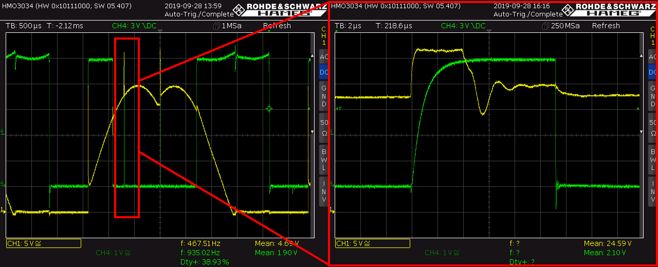
  • GHx, GLx series resistors: 10R
  • VM-GND Cap: 3.3uF
  • VCP-VDRAIN Cap: 2uF
  • CPL-CPH Cap: 2uF
  • VGLS-GND Cap: 2uF
  • PWM Mode: 1-PWM
  • IDRIVE: 700/1400 mA
  • VDS Level: 1V
  • MOSFET Total Gate Charge: 75nC
  • MOSFET Gate-to-Drain Charge: 11nC
  • Motor phase to phase inductance: 10uH
  • Motor phase to phase resistance: 35mOhm
  • Series inductors: 1uH ,3.4mOhm (on the board)

VM remains steady at 11.7V and VCP at 34.5V (VDRAIN + 10.5V)

Low side MOSFETs operation are normal.

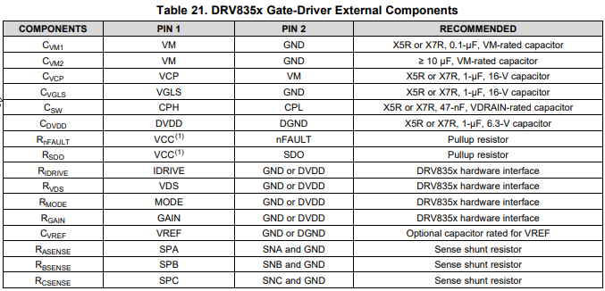
Below are the gate voltages of the high-side MOSFETs and the drivers nFAULT output when driving the motor at 100% PWM duty (there is no switching of MOSFETs except at hall transitions). 

We expected GHA and GHB voltages to be similar to GHC.

There are some narrow peaks at which the nFAULT goes high and the gate voltage rises (but not to the value that it is supposed rise). But this peaks last only 4us, which corresponds to TDRIVE value.

The datasheet states that "If at the end of the T_DRIVE period the VGS voltage has not reached the correct threshold the gate driver will report a fault.", and we think that this peak corresponds to this situation.

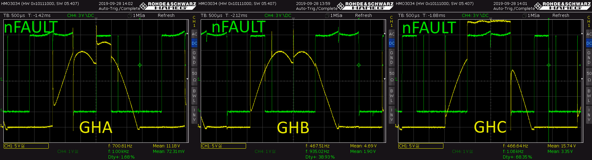
Below is the zoomed view of one of these peaks.

Note that gate voltage reaches only to around 32V (VDRAIN + 8V) where it should have reached 34.5V (VDRAIN + 10.5V).

We have tried the following so far but the problem remained the same.

  • Lowered the gate drive current (IDRIVE) to 450/900 mA
  • Raised the gate drive current (IDRIVE) to 1/2 A
  • Lowered the series GHx resistor values to 3R3 (originally was 10R)
  • Lowered the supply voltage to 16V (originally was 24V)
  • Tried another board in case there were some soldering defects; the problem was essentially same except this time GHB was normal and GHA and GHC were not in that board.

We would be glad to hear from you if you have any idea what this problem is related to.

Regards,

Kursad

  • Kursad,

    Thanks for posting on the MD forum

    Please include a schematic. It seems like many of your on board caps are the wrong values and this will likely cause the issues you are seeing. Please check the EVM schematic below or the datasheet for the recommended values.

    http://www.ti.com/lit/zip/slvc742

    Regards,

    -Adam

  • Hello Adam,

    We have powered up another (third) board with different IDRIVE values and series gate resistors (IDRIVE: 300/600mA, Rgate: 33R). This time there wasn't any problems related to high side MOSFET gates and there wasn't any nFAULT outputs. Is it possible that we broke the previous two DRV8353R gate drivers by using it with a high IDRIVE value?

    I've previously wrote that VM-GND capacitor is 3.3uF but I've checked that again and found out that it was close to 30uF, so it is larger than the recommended 10uF.

    Only other big difference I found was that Csw capacitor value is too big compared to the recommended value (1uF vs. 47nF). Is this a problem?

    Unfortunately I can't include the actual schematics. But the design is almost same as the typical application in the datasheet. Final working values and additional components are shown in the picture below.

    Regards,

    Kursad

  • After using for about an hour, one of the high side gate drivers is broken now. Driver configuration is same as the one in the previous post.

  • Kursad,

    If you use a DMM to compare this unit to a known good unit, do you see any pins which are shorted or open where they shouldn't be? This may help us identify which block of the chip is getting damaged.

    Please use a scope to check the Gate to Source voltage of all FETs as close to the DRV as possible while it is running, make sure it's between the 33R and the DRV as this is the true voltage the DRV will see. We want to check for overshoot and undershoot at either the gate or source lines.

    What is the purpose of the added inductors in the motor lines?

    The CPH/CPL cap being bigger than recommended will likely cause issue as the charge pump is designed for the value in the datasheet and using a different value has not been validated. Likely this is damaging the charge pump.

    Regards,

    -Adam