This thread has been locked.

If you have a related question, please click the "Ask a related question" button in the top right corner. The newly created question will be automatically linked to this question.

DRV8412: Parallel full bridge more only working in one direction

Part Number: DRV8412

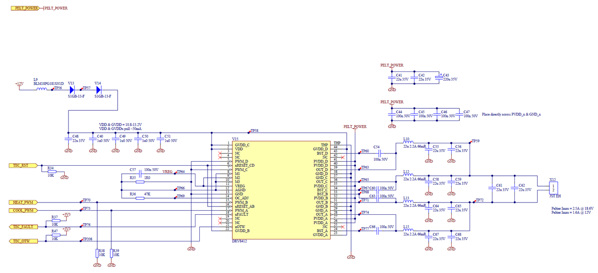
I am using a DRV8412 in parallel full bridge mode 3, driving a peltier. I have followed the circuit in the Figure 17 of the datasheet. PWM is 200kHz. Peltier current 1.5Amax.

What I am seeing is that the bridge works fine in one direction using PWM_A (with PWM_B set to 0V), i.e. channels A/B switching nicely, and channels C/D driving low continuously to sink the return current.

But when I attempt to reverse the direction using PWM_B (with PWM_A set to 0V), I see channels C/D switching nicely, but channels A/B do not drive low, and so there is no current flow.

I have the same issue on multiple boards so not a soldering issue. All voltages check out ok, no faults reported either.

Any idea what might be explaining this?

Thanks,

Ian

  • You will probably ask about the diode arrangement providing power to GVDD...I run the system at around 13.5V and the diodes just soak up some of the excess volts. The behavior mentioned above does occur with GVDD at 12V. I don't think this is a contributor, as GVDD is clean and 12V.

  • Hi Ian,

    Have you tried reversing the order of operation; using PWM_B (with PWM_A set to 0V) then using PWM_A (with PWM_B set to 0V)?

    The reason I ask is that Channels A/B could see a possible overcurrent when discharging the capacitors C55, C56, C58, and C59. By reversing the order, this should provide a clue.

    If Channels C/D show the same behavior, please note section 7.4 of the datasheet:

    In operation modes 1, 2, and 4 (CBC current limit is used), once the CBC current limit is hit, the driver will be deactivated until the next PWM cycle starts. However, in order for the output to be recovered, the PWM input corresponding to that driver in CBC must be toggled. Because of this, CBC mode does not support operation when one half-bridge PWM input is tied to dc logic level.

    To reset the outputs, the outputs a small pulse should be applied to PWM_B at the end of the PWM cycle.