This thread has been locked.

If you have a related question, please click the "Ask a related question" button in the top right corner. The newly created question will be automatically linked to this question.

DRV8835: doesn't work with hobby servo

Part Number: DRV8835
Other Parts Discussed in Thread: DRV8830, DRV8832

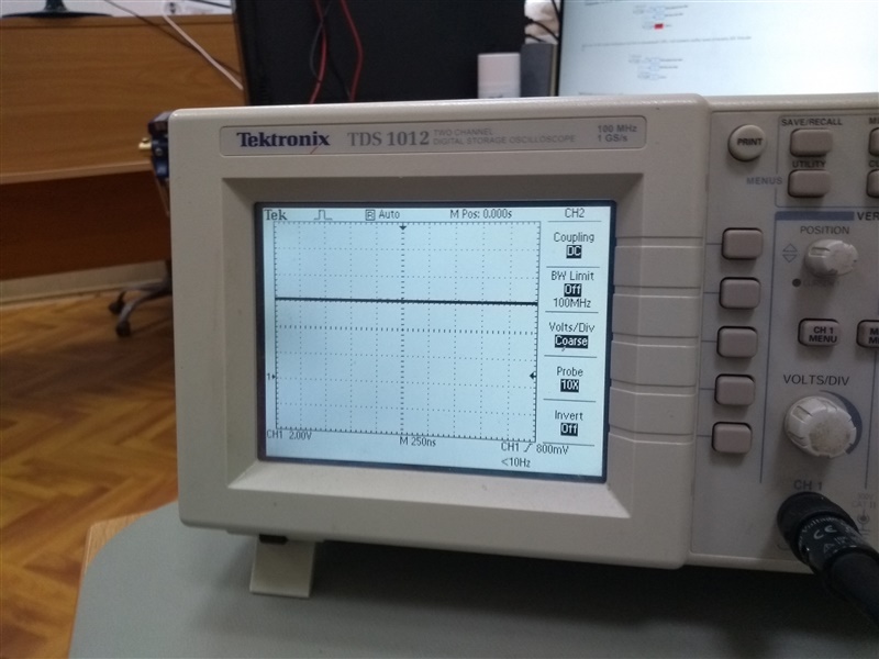
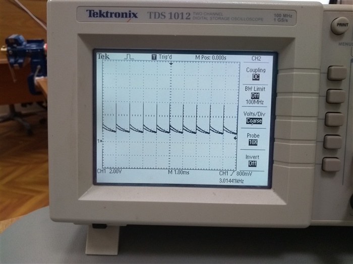
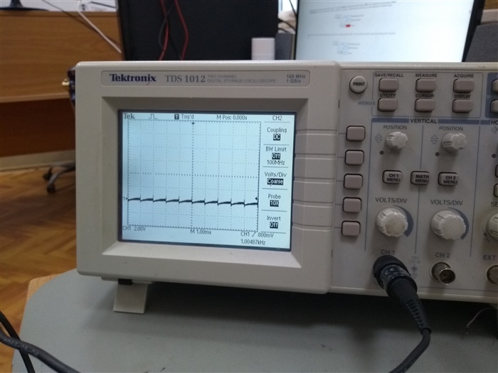
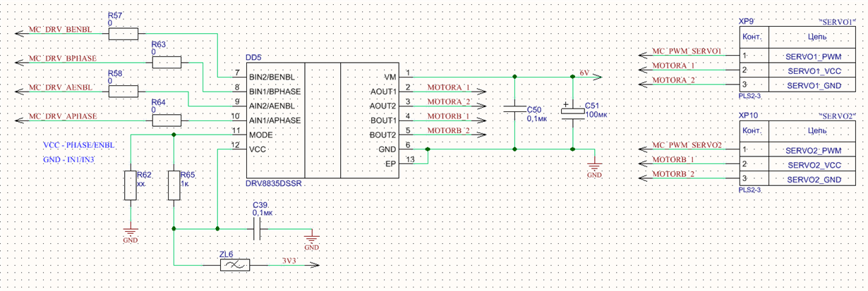
Hello! In my project I decided to use DRV8835DSSR. And i got a problem: the micro servos KST X08H V5 and MS325 does not work when power is connected through the driver. The driver is used in this case in key mode, simply as a voltage switch (on/off). This is done so that there is the potential to use a DC motor instead of a servo and control the rotation speed via PWM through the driver. MODE = VCC, AENBL = HIGH level, APHASE = HIGH level from the STM32 F205RET microcontroller. At the output AOUT1 there is a low level (I connect it to the black wire of servo), at AOUT2 there is a high level 6V (I connect it to the red wire of servo), but this voltage is when servo is not connected. The control signal (yellow wire) comes directly from the microcontroller. On the oscilloscope i watched a control signal and everything is fine, the frequency is 50 Hz, the pulse duration is 1500 microseconds. If powered directly from the voltage 6V, the servo works, angle changes. However, if through the driver, there are dips on the VCC and GND signals, DRV8835DSSR restarts every 1 ms. I tried to connect driver to the DC motor from the disassembled servo X08H and it works, as well as other motor Maxon 2W also works. But servo doesnt work through this driver. Maybe you can help, how to fix this problem? Any idea? I want to use servo, but also want a potential opportunity to use DC motor. I use a standart connect circuit, as specified in the datasheet. I send you the circuit part and waveforms. Thank you!

  •  

    6V with connected servo (OUT2)

  • Hi Oleg,

    You appear to be experiencing an overcurrent event. The DRV8835 has overcurrent protection. If the current exceeds the Iocp level for more the tDEG, the outputs are disabled. This repeats every 1ms.

    There are typically two reasons for this.

    1) there is a capacitor placed across the motor terminals and the inrush current causes the overcurrent.

    2) the stall current of the motor is greater than the DRV8835 can provide

    If you have access to a current probe, please use it to determine if the reason is inrush current or stall current. If inrush current adding inductance between the outputs and the motor terminals may help.

  • Thank you for answer, Rick!

    I understand that the ripple on the waveform it's OVP.

    For 1st point: do you propose to reduce the capacity C51?

    For 2nd point: servo running with no load now.

    "If inrush current adding inductance between the outputs and the motor terminals may help." What kind of inductance? Which value?

    I found one thing on the forum:

    https://e2e.ti.com/support/motor-drivers/f/38/p/654975/2405592?tisearch=e2e-sitesearch

    "I do not recommend the DRV8835 because I think its speed regulation feature will interfere with any closed-loop control algorithm you may want to implement."

    What is "speed regulation feature"? Maybe it can conflict with chip that is inside servo? It's chinese chip SZD900 - H-Bridge Driver.

    "SZD900 is a special integrated circuit for controlling digital servo with wide working voltage. The peripheral circuit is simple, with 4 PWM output control terminals to drive H-bridge. The parameters that can be set are: dead zone, pulse width step, gain, PWM maximum duty cycle, midpoint position and input signal recognition range, etc. 1520us and 760us signal"

    I am asking about this because DC Motor which located inside this servo work, when i directly run it by DRV8835 by connecting wires to outputs of motor. But it doesnt work under normal connection how should this servo work (3 pin: vcc, gnd, control pwm signal). I think inrush starting  current should be the same, but apparently I'm wrong.

    Best Regards,
    Oleg Shishkunov 

  • Hi Oleg,

    I understand that the ripple on the waveform it's OVP.


    Just to confirm, the ripple is overcurrent (OCP) not overvoltage (OVP).

    For 1st point: do you propose to reduce the capacity C51?


    No, there is no need to reduce the C51.

    For 2nd point: servo running with no load now.

    "If inrush current adding inductance between the outputs and the motor terminals may help." What kind of inductance? Which value?


    Please see comments below about connecting a controller in series with another controller.

    I found one thing on the forum:

    https://e2e.ti.com/support/motor-drivers/f/38/p/654975/2405592?tisearch=e2e-sitesearch

    "I do not recommend the DRV8835 because I think its speed regulation feature will interfere with any closed-loop control algorithm you may want to implement."

    What is "speed regulation feature"? Maybe it can conflict with chip that is inside servo? It's chinese chip SZD900 - H-Bridge Driver.

    This was a typo. The DRV8830 and DRV8832 have an automatic speed regulation. The DRV8835 does not.

    "SZD900 is a special integrated circuit for controlling digital servo with wide working voltage. The peripheral circuit is simple, with 4 PWM output control terminals to drive H-bridge. The parameters that can be set are: dead zone, pulse width step, gain, PWM maximum duty cycle, midpoint position and input signal recognition range, etc. 1520us and 760us signal"

    I am asking about this because DC Motor which located inside this servo work, when i directly run it by DRV8835 by connecting wires to outputs of motor. But it doesnt work under normal connection how should this servo work (3 pin: vcc, gnd, control pwm signal). I think inrush starting  current should be the same, but apparently I'm wrong.


    Comments about connection motor controllers in series:

    The DRV8835 is intended to drive a motor. If the DRV8835 to control the motor, it should work unless the stall current is too high and creates an overcurrent event.

    You will have to determine how the normal connection works. We are not familiar with the SZD900 and how it is connected to the motor.