This thread has been locked.

If you have a related question, please click the "Ask a related question" button in the top right corner. The newly created question will be automatically linked to this question.

DRV8306EVM: DRV8306EVM

Part Number: DRV8306EVM
Other Parts Discussed in Thread: DRV8306

Hi all,

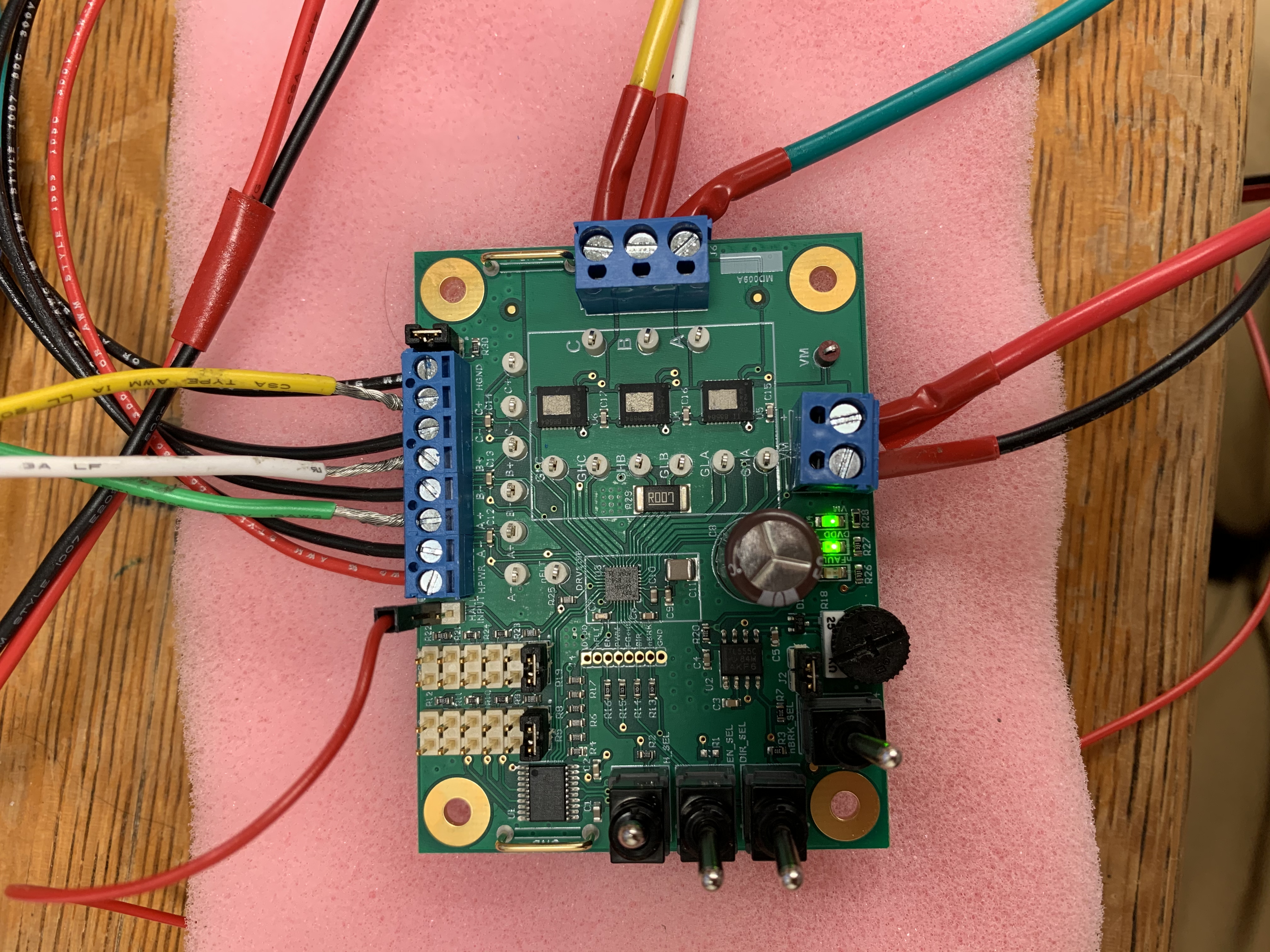
I'm trying to use a DRV8306EVM to drive a 3-phase BLDC motor equipped with Hall sensors. All wires are connected according to the user guide of the module but motor just doesn't move at all.

1-the voltage input at VM terminal is 12V (in the range of 6-38V as you mentioned), the current is not limited;
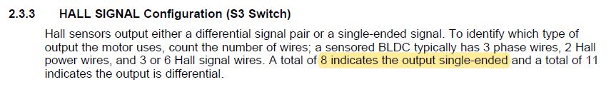
2-swith (S4) is set to run, switch (S3) is set to single-ended (there are 8 pinouts according to the user guide page 7, 2.3.3), swith (S2) is set to enable;
3-jumper JP1 is removed, pin 2 in JP1 is connected to an external power supply of 5V, all of the "-" terminals (low side) of Hall sensors are common grounded.;
4-There are 8 pinouts from the motor, 3 phase wires, 2 Hall power wires and 3 Hall signal wires, according to page 7, 2.3.3 of the user guide, I selected single ended at switch S3. 
Could anyone suggest what could be the possible reason? Really looking for technical support. Thanks a lot
  • Kuo,

    Thanks for posting on the MD forum!

    Please show a picture of your setup in the "running" state.

    Do you have a scope that you can use?

    Regards,

    -Adam

  • Hi Adam,

    Thank you so much for your response. The setup of the running state is as shown above. Yes, I have a scope for inspection.

    Kuo

  • Kuo,

    Sorry for the delay.

    Did you get this working?

    If not could you update me on your attempts or progress?

    Regards,

    -Adam

  • Hi Adam,

    Thank you for your response. No there is no further progress since last update. I still cannot figure out what the reason is. Could you provide some suggestion?

    Kuo

  • Kuo,

    A few things don't match here:

    1. You mention having S3 in Single-Ended mode but you are providing all 8 hall sensor wires. Is your motor single-ended or differential hall?
    2. The User's Guide says the following: "For single ended, make JP1 and JP2 jumpers are installed." You mention using Single-Ended but that JP1 is uninstalled and 5V is provided. The Hall inputs on the DRV8306 are tolerant up to DVDD which is 3.3V. Powering the halls with 5V will likely damage the DRV8306.

    Likely the hall inputs are damaged or the connections to the board are incorrect unfortunately but we can correct this.

    Regards,

    -Adam

  • Hi Adam,

    Just to answer your question:

    1-I selected signle-ended according to the user guide page 7 (as shown below) since my motor has 8 pinouts in total

    2-Since my Hall sensors need a 5V power supply, I removed JP1, also according to the user guide page 7. But you make a good point. Could you suggest any solution that I can take in my case to power the Hall sensors with 5 V without damaging DRV8306?

  • Kuo,

    My mistake, I misunderstood.

    It is okay to power the halls with 5V as long as the halls are open drain type. If they are Open Drain type then the pull up voltage present due to the selection of the S3 switch and U1 will control the voltage that the MCU sees when the halls are HIGH.

    I am still not sure why you have connections made to A-, B-, and C- if your hall sensors are single ended. These three connections are only to be used if the hall sensors are differential.

    Can you show me the motor and motor datasheet?

    Do you have a second EVM you can try?

    Regards,

    -Adam

  • Hi Adam,

    Thank you for your response. I made these three connections by supposing that each channel of the phase generating a single-ended signal. Since there are 3 phase, there are three single-ended signals to the driver board, and the '-' sides are common grounded. I do have another non-TI EVM in hand and it works well in motion control but it cannot conduct a torque control when the motor stops at some certain position. That's the reason I search for another EVM. The motor is actually an OEM actuator in the exhaust recirculation loop onboard our tested engine platform so I don't have any available datasheet about the motor. The attached below is the pinout diagram of the motor. Please me know if you have any suggestion in this case. Thanks again.

    Sincerely,

    Kuo

  • Kuo,

    I'm not sure what to advise here as we don't know enough about this motor and you don't have a datasheet.

    Regards,

    -Adam

  • Kuo,

    I would check using a scope that the halls are active LOW and that they are separated by 120 degrees.

    Regards,

    -Adam

  • Hi Adam,

    Thank you for your advices. I'll let you know if there is any progress.

    Regards,

    Kuo