This thread has been locked.

If you have a related question, please click the "Ask a related question" button in the top right corner. The newly created question will be automatically linked to this question.

DRV8323R: Synchronous Mode doesn't drive as per Table 4 (?)

Part Number: DRV8323R

Hello Support,

I have built an evaluation board for DRV8323RH. I have left the mode pin floating (1xPWM mode), IDRIVE pin is also floating (120/240 mA), Gain pin floating (unused current sense for now) and disabled VDS.

I have then ran the commutation as per Table 4. What I observe is the following:

1) 5kHz PWM applied is indeed delivered to the chip. And I can see it on Phase A.

2) PWM only appears on Phase A.

3) Phase B is in Hi-Z

4) Phase C goes to ground every 3 steps and then back up.

If I reverse direction through INHC, Phase A and Phase C swap behaviours.

5) Connections to all three phases are identical.

6) When INLC is driven low (full stop), all low side FETs are indeed ON., and all high side FETs are off.

7) nFAULT throughout is high, indicating no fault.

8) I have double and triple checked INHx and INLx connections, they are fine.

9) I am using IPT004N03L FETs

10) Even when trying to align INLA, INHB and INLB are all high, Phase A is in PWM, Phase B is in Hi-Z and Phase C is low.

11) I have measured the voltage on MODE pin and it is 2V.

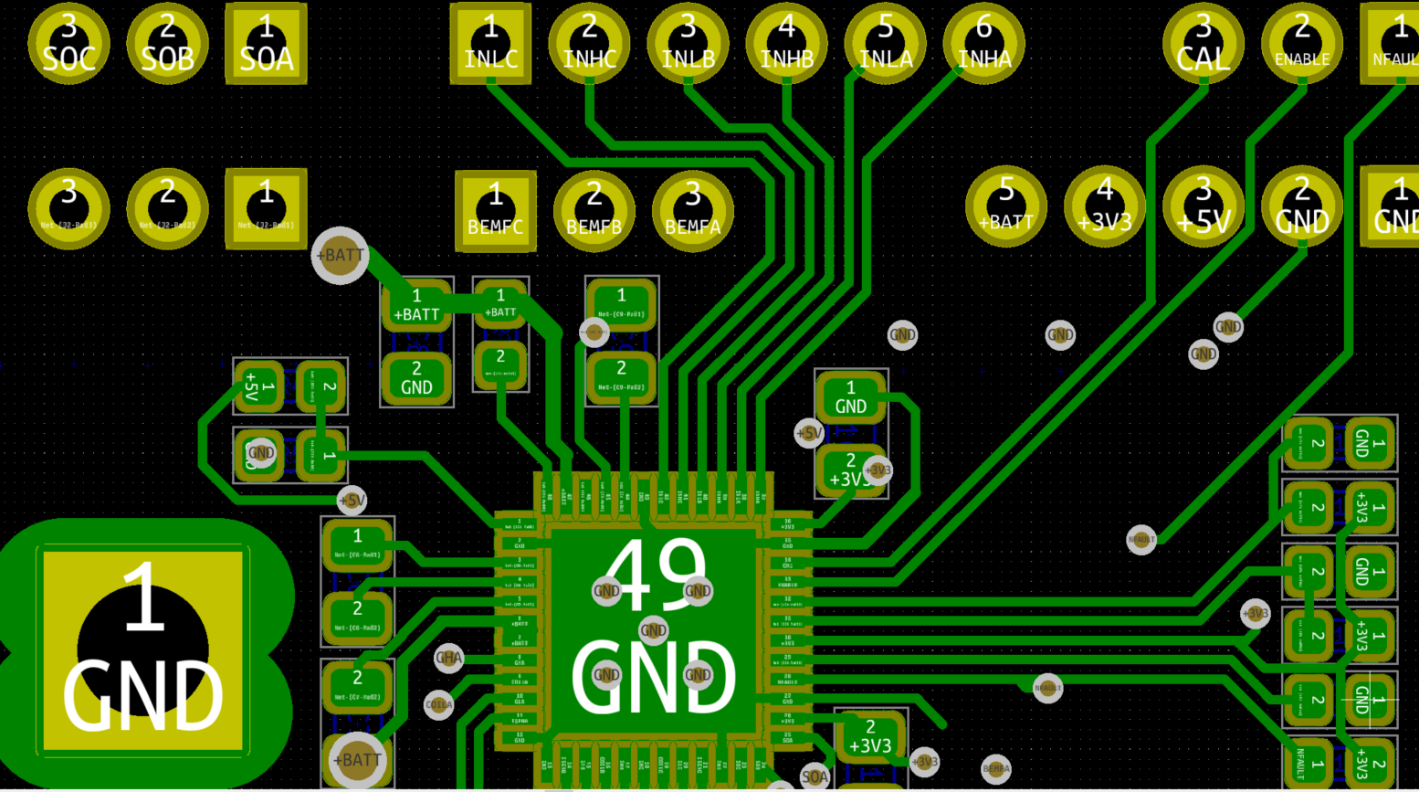
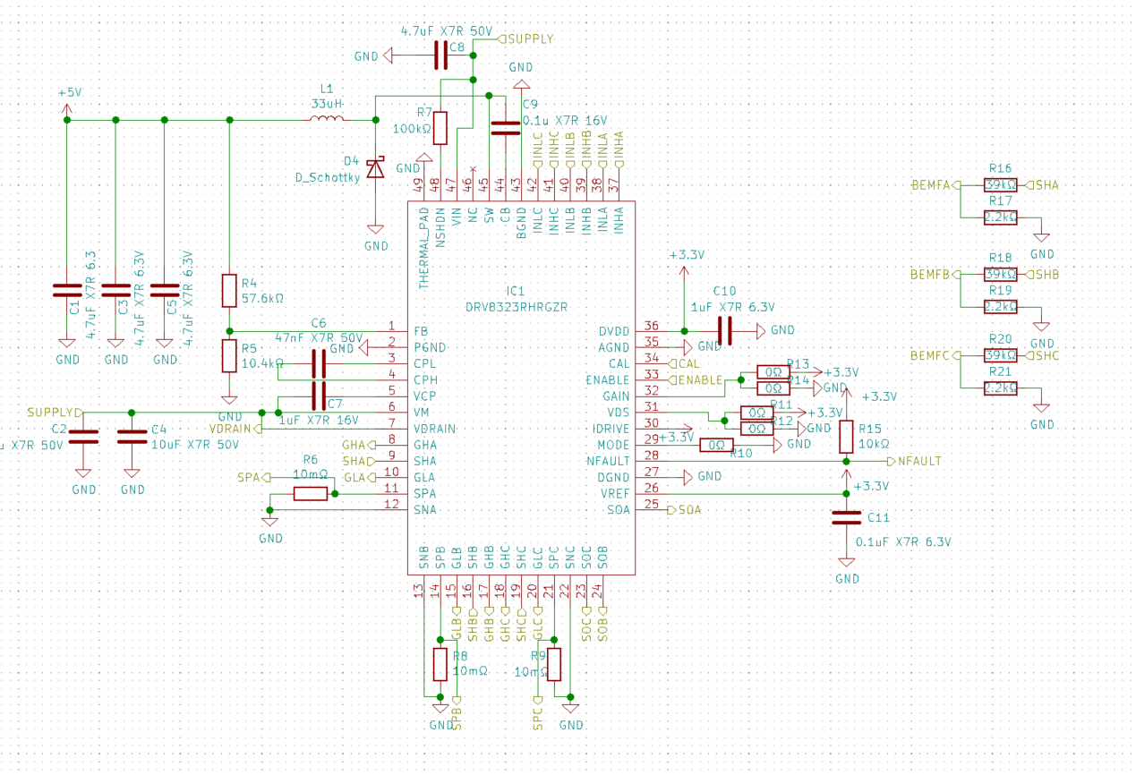
I attatch the layout and schematics.

Many thanks,

Jakub

  • Is there perhaps some sort of initialization protocol I am missing? 

    What I am doing in code is:

    a) init all pins

    b) setup PWM

    c) drive INLC high

    d) Drive Enable high

    e) startup():

    -align (INLA, INHB, INLB = 1)

    - setup an interrupt to go through steps 1 to 6 and repeat (the signals on INHx and INLx are all what I am expecting after measuring them)

    - for testing I am driving just three resistors 300Ohm each, to protect my motors for now.

    EDIT: to clarify - I cut the IDRIVE track. 1/2 A was way too much. 

    EDIT2: I just put the device in 3xPWM mode and it works just fine.... Why wont 1xPWM work?

  • Jakub,

    Thanks for posting on the MD forum!

    How are you driving the INLA/INHB/INLB pins? With the MCU? Have you checked at the device pins itself to make sure the MCU is operating as expected?

    Most of our customers use 1x mode because they have hall sensors on their motor, will you be using hall sensors?

    When you are checking the outputs, what are you measuring and how are you concluding if the gates are ON, OFF, or Hi-Z?

    Regards,

    -Adam

  • Hi Adam,

    thank you for a quick follow up! At the moment I have a PyBoard driving the pins. I have indeed checked the waveforms and they are all good. I have even gone as far as doing continuity checks between PyBoard and the chip. This is confirmed by running the 3xPWM mode, which runs just fine.

    When checking I measure the gate voltages and the SHx nodes. If the MOSFETS are ON, the appropriate gate voltage will be Vm+11V or 11V and SHx will be at Vm or at GND. If the bridge is in HiZ the SHx is expected to be at VM and the gate voltages are VM (high side) and 0V (low side). These results are obtained for when no load is connected.

    I wont have Hall sensors. The reason for using 1xPWM, is that it is computationally inexpensive so that a simple PyBoard can run the motor quite quickly. But yes, eventually I will move on to STM or equivalent. And will use a different mode.

    For now 1xPWM would be optimal...

    Thank you,

    Jakub

  • Jakub,

    Please double check your alignment of hall signals and PWM input signals, then check the commutation pattern since you are forcing it with the MCU.

    Regards,

    -Adam

  • Adam,

    Unless there is more to the timing than the gray code presented in Table 4, the driving pattern is fine. It was 3 square waves 120 degrees apart.

    How is that information stored on the chip? Is it possible that reflow soldering could have affected it (~300 degC)?

    I have successfully moved on with 3xPWM and solving this is not critical to us, but I am just curious where I or something else went wrong.

    Jakub

  • Jakub,

    The programming is as shown in the datasheet and the programming can't be compromised with heat.

    If you could provide us any scope images of the inputs and outputs in 1xPWM we can debug further.

    Regards,

    -Adam