This thread has been locked.

If you have a related question, please click the "Ask a related question" button in the top right corner. The newly created question will be automatically linked to this question.

DRV8908-Q1: Unable to get the motor to work

Part Number: DRV8908-Q1

Hello,

I am using PDRV8908 to driver 4 motors. To start with, I was trying to turn one motor first, which I am having trouble.

Following is the driver connection schematic:
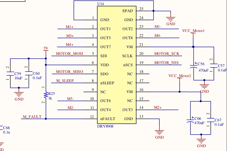

I was trying to run the motor in PWM mode, following the instructions.
* nSLEEP_pin = 1;
* PWM_CTRL_1 = 0x3
* PWM_MAP_CTRL_1 = 0x8
* PWM_FREQ_CTRL_1 = 0x0F
* PWM_DUTY_CTRL_1 = 0xCC
* PWM_DUTY_CTRL_2 = 0x00

I verified these values in the registers, but the motor doesn't turn. The IC_STAT register reads 0xC0.

Please help me in getting this to work.

Thanks,

Naveen.

  • Hi Naveen,

    Have you tried looking at the outputs with no load?

    This is a good starting point to confirm the device is operational.

    After the device is confirmed to provide the proper outputs, please add the load and watch the nFAULT signal? Is nFAULT high or low? If low investigate the reason for nFAULT being low. There is a fault table available in the datasheet to assist in determining the cause of the fault.

    If nFAULT is high and the motor does not turn, please provide scope captures of the output voltages when the motor is starting. 

  • Hi Rick,

    I tried disconnecting the load from the output and checked the outputs. They are still 0 and nFault remains at 1.

    Although my end goal is to operate the motors in PWM mode, I also tried to turn it in continuous mode (with no load), by setting OP_CTRL_1 to 0x6. What I noticed is, the IC_Status is set to 0xD1 and nFault pin was 0 (with OLD_STAT_1 as 0x6).

    When I connected the motor and tried the same settings, the IC_Status read 0xD9 and the nFault pin was 0.

    What could be wrong in what I am trying to do?

    Update: When operating in continuous mode, I saw the voltage fluctuating at the output pins. (Since I don't have access to a scope, I cannot get the waveforms for the output)

    Thanks,

    Naveen.

  • Hi Naveen,

    With no access to scope, it may be difficult to debug.

    For now, please focus on getting the outputs enabled at 100% with no load.

    Once you have the outputs enabled, then try using PWM and vary the duty cycles. The duty cycle should be observable by measuring the DC voltage at the outputs. A rough estimate is the measured DC voltage at the outputs should be ~VM X duty cycle.

    After the above steps, the final step is to add the load. 

    What are the specifications of the load (R/L/stall current/ voltage rating)?